Actuate display using ESP32
3 minute read
Intro
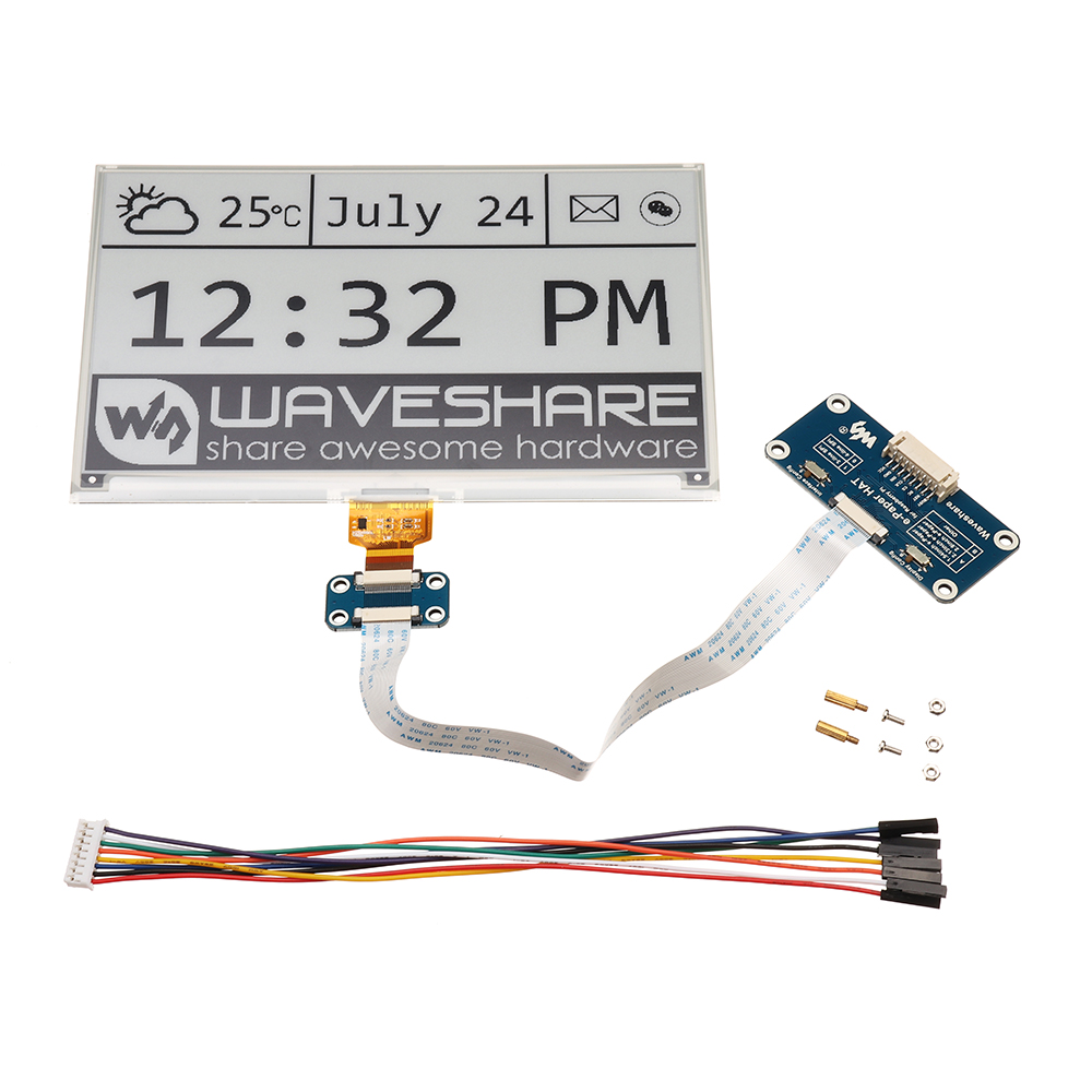
In this part, a figure, living on the Home Assistant server, will be displayed on a 7.5 inch e-paper using an ESP32-based board.
Used components:
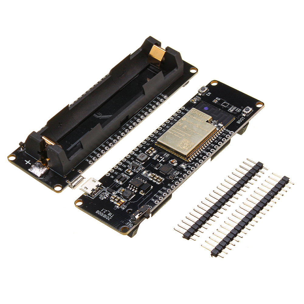
Esp 32: pinout
The SPI interface of the ESP32 will be used to control the display. The pins of SPI quickly get confusing:
- Names of the different interfaces of SPI aren’t very consistently used (MOSI, SPI D, SD0, SS, CS, SCK, CLK, SD1, … ) + you have to pay attention to the difference between IO pins and GPIO pins in the ESP32 datasheet.
- The ports labeled on the ESP-board with clk, SD0, SD1, … are linked to an SPI bus. But one only used to flash the device, not used for communication with external devices … .
In the ESP32-wrover datasheet, it can be found two SPI busses are available for external communication: VSPI and HSPI.
Below, the overview is provided to which pins these two busses correspond with. The last column is mainly added to be able to check if custom esp32 boards (like this one) also respect the GPIO labels marked on the board. (The esp32 feet are still large enough to check with a multi-meter.)
| VSPI | GPIO (pin label) | Name ESP32-wrover chip | No. ESP32 Chip |
|---|---|---|---|
| MOSI | 23 | VSPI D | 37 |
| MISO | 19 | VSPI Q | 31 |
| SCK | 18 | VSPI CLK | 30 |
| SS | 5 | VSPI CS | 29 |
HSPI:
| HSPI | GPIO (pin number board) | Name ESP32-wrover chip | No. ESP32 Chip |
|---|---|---|---|
| MOSI | 13 | HSPI D | 16 |
| MISO | 12 | HSPI Q | 14 |
| SCK | 14 | HSPI CLK | 13 |
| SS | 15 | HSPI CS | 23 |
For the BUSY, reset and DC pin, any suitable DIO can be selected. This is how it looks in my configuration / script for VSPI:
static const uint8_t EPD_BUSY = 4;  // to EPD BUSY
static const uint8_t EPD_CS   = 5;  // to EPD CS
static const uint8_t EPD_RST  = 21; // to EPD RST
static const uint8_t EPD_DC   = 22; // to EPD DC
static const uint8_t EPD_SCK  = 18; // to EPD CLK
static const uint8_t EPD_MISO = 19; // Master-In Slave-Out not used, as no data from display
static const uint8_t EPD_MOSI = 23; // to EPD DIN
Esp 32: the code
The great GxEPD2 library will be used for drawing on the e-paper display.
- A good example to verify if your pinout is correct and libraries are installed correctly, is to use this implementation: Weather display
- For our purposes the default example in the library - GxEPD2_WiFi_Example.ino - will be modified to fit our purposes. The main challenge was to make it download an image from a local website (home assistant at http://192.168.0.205:8123/local/black2.bmp ).
The resulting script can be found here, if you want to test it out:
- A Credentials.h file is expected which contains your WiFi settings
const char* ssid     = "xxx";
const char* password = "xxx";
- You have to copy a small bitmap image (.bmp) in your xxx/www folder in home assistant (Home Assistant: External files), or generate content through scripts (Home assistant: content creation)
- Pay attention to set the SleepDuration, WakeupTime, SleepTime, … in the script when the system should remain awake
- Of course, change 192.168.0.205:8123 to your own home assistant settings
Others
if you want to play around with displaying any image, I use ImageMagick to convert images to bitmaps consisting of 3D arrays (and not 4D) with the command:
convert plot.png -resize 640x384 -type GrayScale -depth 8 black2.bmp