Mail detection version two
8 minute read
Goal
Get notified when a letter / package is dropped in your mail box (the real mail, not e-mail). Notifications are implemented by integration in my home assistant. Alternatives - sending an e-mail, text message, … - could be useful extensions.
Concept
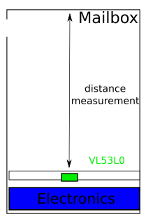
A distance sensor senses upwards in the mailbox, if a package is on top of it, the distance will be small. If the box is empty a larger distance is sensed.
The design is made to work with two AA-batteries (most common type in EU).
Concept
Short summary
- An ESP8266 will send MQTT messages over wifi to report the distance measured in the mailbox.
- There is a mismatch in voltage between two AA-batteries (2.4ish V) and the ESP (requires 3.3V). To avoid having a boost dc-converter turned on 24/7 and reduce battery life (significantly), the dc-converter and ESP will periodically get enabled/disabled by an Arduino pro mini.
- The status of the ESP8266 gets communicated to the pro mini in a simple way.
- The Arduino pro mini can work up to 1.8V. It does require setting the fuses of the microcontroller to the appropriate values. This will be done by burning a specific bootloader.
- Compared to the first version of the mailbox detection, Tasmota will not be used. This to further minimize the time the ESP8266 is alive and connected to wifi.
Layout
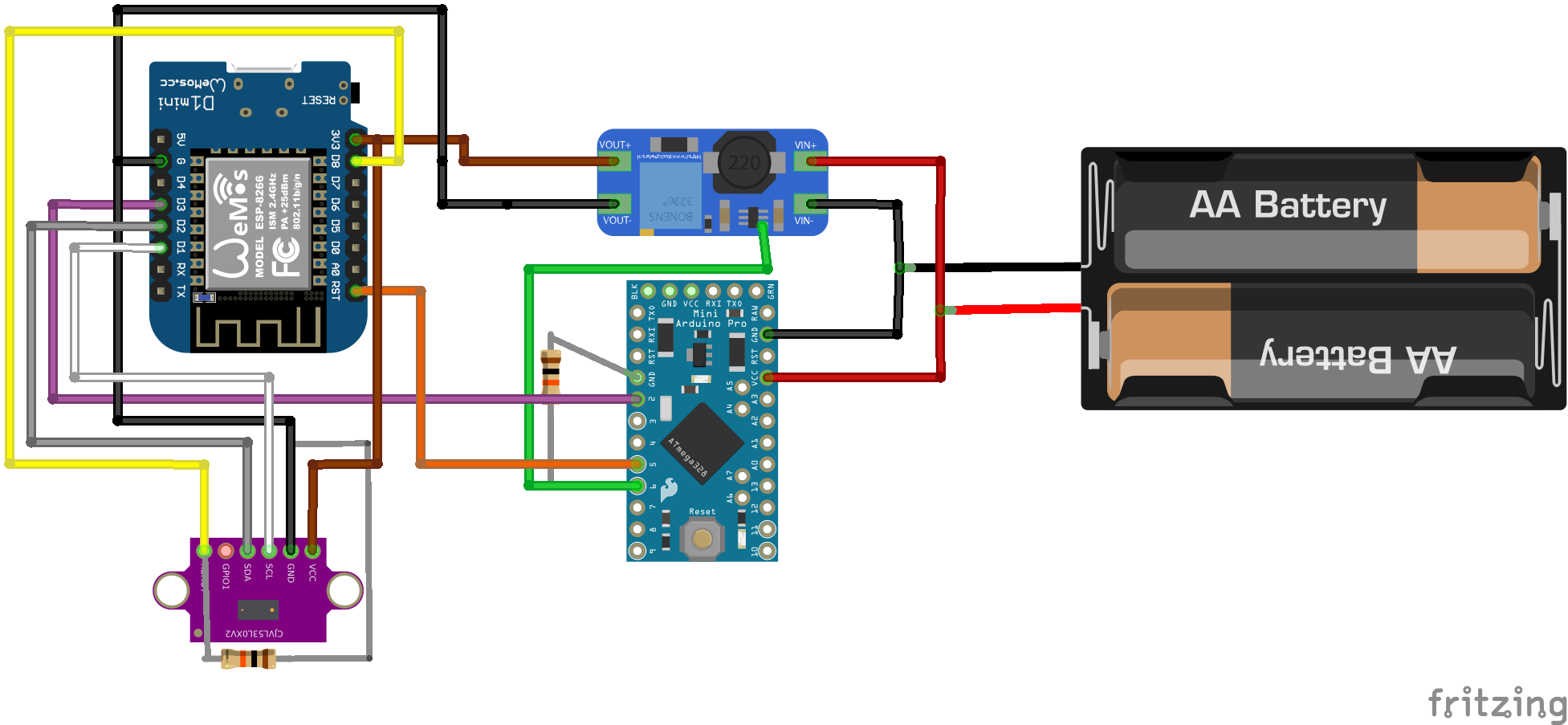
Wiring layout
Notes:
- The pins has been selected taking the internal pullup and pulldown resistors into consideration. Consider this when making modifications.
- To avoid unnecessary power losses, the wemos is directly fed to its 3.3V pin and not through the regular 5V (see the schematic of the Wemos mini). The same applies for the arduino pro mini (Vcc instead of Vraw)
Prerequisites
Of course, it’s fundamental wifi signals need to reach your mailbox :). If not, you can already create wifi repeaters for less than 3 euro with an esp8266 / esp32 by using this software … .
Required components
- Wemos D1 mini, to connect to wifi (and send mqtt messages)
- Arduino pro mini or clone: controls the dc-converter and communicates with esp
- MT3608: step up DC-DC to generate supply for wemos
- VL53L0Xv2 sensor, measures the distance accurately according the time-of-flight principle (for some reason much cheaper on aliexpress compared to banggood example)
- Two AA-batteries
- Few (10k) resistors
- Another arduino or alternative to flash the pro mini as ISP, I’m using an arduino Mega 2560 but should work with all kinds of arduino’s or flash tools.
To reuse the available sketches for the Wemos, it is assumed an mqtt broker is available (in my case the board running home assistant). In case it’s not available, it shouldn’t be too cumbersome to make the Wemos send an e-mail or even a text message… .
Step 1: Flash bootloader on arduino pro mini
Why
According to the atmega328p datasheet, the frequency needs to be lower than 4MHz to be able to work at 1.8V. To achieve this we need to set the fuses of the chip, luckily this can be easily done in the arduino environment.
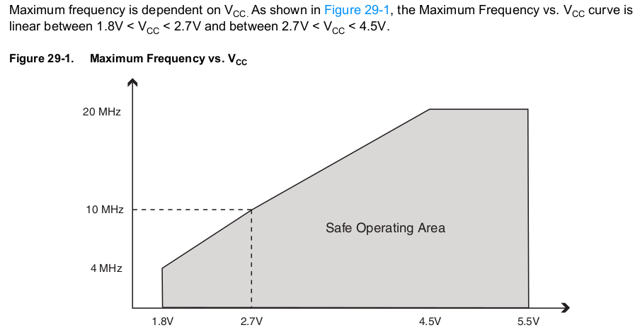
MHz vs minimum voltage
The lower the frequency, the lower the current consumption. Since the arduino doesn’t need to do anything fancy, there is no reason to choose a high frequency.
Programming using Arduino IDE
- Prepare to program the pro mini through another arduino, you can find a lot of tutorials “Arduino As ISP” on the web (official arduino site). Double check in the ArduinoISP.ino sketch which pin is the reset pin, I’m using Arduino Mega 2560 as ISP which has pin 10 as reset pin.
- upload the sketch from the default examples " ArduinoISP.ino" to your programmer (the Mega 2650 in my case)
- make the wiring connections to the pro mini: MISO - MISO, MOSI-MOSI, SCK-SCK, RST (pro mini) to 10 (Mega), Vraw (pro mini) - 5V (Mega), GND-GND
- open an example sketch like blink.ino to check if you can sucessfully upload. Select the board “Tools–>Arduino pro or pro mini”, Port remains the “arduino Mega” and upload the sketch using “Sketch –> Upload using Programmer” instead of the standard “Upload” button.
- Burn bootloader (ironically, there is no need for a bootloader since we’re flashing following ISP. But if we don’t burn the bootloader, the fuses of the microcontroller don’t get set … .)
- follow the steps described on the MiniCore github: https://github.com/MCUdude/MiniCore#how-to-install
- Select the following settings: ATmega328, Internal 1 MHz, BOD 1.8V, Variant: 328P, Bootloader: Yes
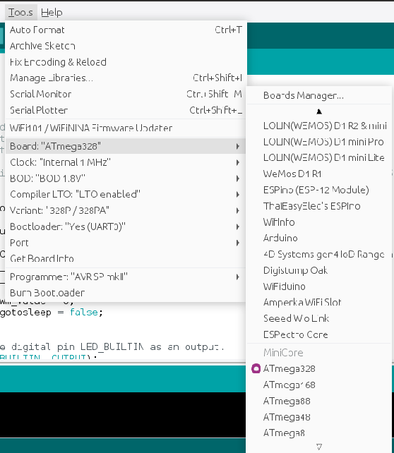
Arduino IDE settings
- Press “Burn Bootloader”, if successfully programmed, reboot your pro mini
- Upload a blink sketch “Upload using programmer”. Check the timing of the blinking led now we have changed the oscillator to 1 MHz instead of the default 8 or 16 MHz … .
LEDS
The power led and voltage regulator can be desoldered from the pro mini to decrease power consumption further. Don’t do this before debugging is finished.
Step 2: Prepare DC-DC converter
This is by far the most finicky part of the setup. The MT3608 has by default an enable pin. Unfortunately this one isn’t easily available on the Chinese boards. You might want a few spare converters, just in case … ;).
Things to modify to the board:
- Cut the trace between the enable and Vin pin. A fresh cutter knife seems just enough to do the trick.
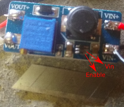
MT3608 modification with cutter knife
- Solder a wire to the enable pin. Do a beep test to make sure the wire is not connected to Vin+.
- Test if the converter gets enabled and disabled by connecting the soldered wire respectively to Vin+ and GND/Vin-.
- Finally, adjust the screw on the potentiometer till your output voltage becomes around 3.3V when the converter is enabled.
Step 3: Wire the components and program ESP and arduino
If this all went succesful, the hard work is over :). Program the intended sketches on the pro mini (through the ISP method) and wemos. The sketches are available at https://github.com/goosst/MailboxDetection.
Some notes on key items to verify / adapt:
- Wemos D1 Mini: one - rather remarkable observation - is that cycling input voltage from 2.3ishV to 3.3V, does not reboot the Wemos automatically. For this reason the ESP is put in deepsleep
ESP.deepSleep(0);so it can be woken up through its reset pin. The deepsleep starts after a successful broadcast of a MQTT message. TTe pro mini needs to cycle the Reset pin of the wemos. Please verify this is working as expected, since the Reset pin is quite sensitive to be in a floating state. - Wemos D1 mini: in configuration.h change the password of your wifi and mqtt broker. Obviously you can change the name of the mqtt message if you want something clearer.
- Arduino pro mini: check in the code how frequent you want to let the converter/ESP wake up and check your mail (by changing the counter in the for loop of 8 second sleep cycles).
  for (int i = 1; i < 20; i++)
  {
    LowPower.powerDown(SLEEP_8S, ADC_OFF, BOD_OFF);
  }
If everything is working, you should see periodic message of the distance being broadcasted in your mqtt broker. (Example below with messages arriving artificially fast every three minutes.)
xxx@tinkerboard:~$ mosquitto_sub -h localhost -t /sensor/ESP8266-6857171/# -u "username" -P "password" -v | ts
Jul 26 06:54:17 /sensor/ESP8266-6857171/data/distance 366
Jul 26 06:54:35 /sensor/ESP8266-6857171/data/distance 366
Jul 26 06:57:24 /sensor/ESP8266-6857171/data/distance 364
Jul 26 07:00:13 /sensor/ESP8266-6857171/data/distance 367
Jul 26 07:03:03 /sensor/ESP8266-6857171/data/distance 367
Jul 26 07:05:52 /sensor/ESP8266-6857171/data/distance 368
(Optional) Step 4: Integration in home assistant
The following steps will be done in the home assistant environment:
- distance of the sensor gets read through the mqtt message
- python script is called to convert this distance to something meaningful
- displayed in home assistant
MQTT sensor
Create a sensor in configuration.yaml, get the exact mqtt message from the console window:
sensor:
  - platform: mqtt
    name: "MailBox"
    state_topic: /sensor/ESP8266-6857171/data/distance
    expire_after: 14400
    unit_of_measurement: "mm"
    payload_available: "Online"
    payload_not_available: "Mailbox sensor Offline"
python script
To convert this distance into a state of the mailbox when a new message arrives, a small python script mailboxstate.py is called.
mailboxstate.py uses the REST api to read the mailbox sensor, and write the converted state of the mailbox to a new variable (mailboxfull). The full script is available at: https://github.com/goosst/HomeAutomation/blob/master/python_scripts/mailboxstate.py, but it will report the following states:
if time_last>now-max_delay:
    #Check if empty (comparison in mm)
    if state_last<100:
        payload='{"state": "Check you post box!"}'
    elif state_last>=100 and state_last<1200:
        payload='{"state": "Post box is empty"}'
    else:
        payload='{"state": "No clue"}'
else:
    payload='{"state": "No update"}'
This script is called everytime the mailbox sensor (from the mqtt message) changes. This is done by defining this in configuraiton.yaml:
shell_command:
  mailboxstate: 'python3 /home/homeassistant/.homeassistant/python_scripts/mailboxstate.py'


automation MailBox:
  - alias: MailBox
    trigger:
      platform: template
      value_template: "{{ (states.sensor.date_time.last_changed - states.sensor.mailbox.last_updated).total_seconds() > 30 }}"
    action:
      service: shell_command.mailboxstate
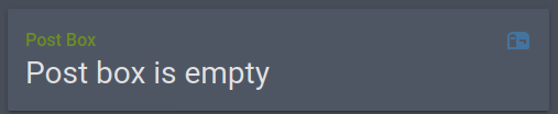
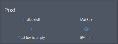
Result
Adding both entities in ui-lovelace results in something like this:
Tasmota setup
Tasmota setup
Other improvements
- 3d print a housing :)
- using pin D8 on the wemos provides a more elegant way to communicate the status to the pro mini without additional software/interfaces.
- custom pcb to get rid of modifications
Appendix
VL53L0X
The pin Xshut is used to enable/disable the sensor, there is an issue however:
- The Xshut pin should be pulled low during our deepsleep to disable the sensor. The only pin which has this behaviour is D8/GPIO15: https://tasmota.github.io/docs/DeepSleep/#esp8266-deep-sleep-side-effects.
- Xshut is active low, so it will try to pull pin D8 high. The big issue here is, GPIO15 should be low during the boot of the ESP8266 or the module will not boot up … .
Solution:
- Connect Xshut to D8
- add an additional pull down resistor to Xshut and GND (here using 2k ohm).
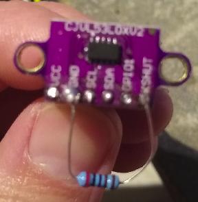
Additional resistor
- Now pin Xshut is low during Deepsleep and high when the ESP is awake!