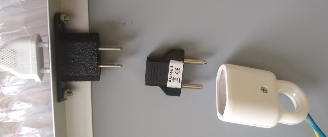
Creating a narrow as possible electricity plug (to integrate behind a mirror).
Goal
I wanted to integrate an electricity plug behind my mirror, which only has a few centimeters of aluminum between the glass and the wall. Only two pins are needed, no ground.
I didn’t immediately find a solution that was - easily - commercially available.
Drill two M4 holes for mounting, drilling two M6 holes for the guidance of the electricity pins
parts put together
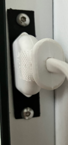
The visible side
Could you get rid of the second US-EU conversion, probably yes … . But feel free to mod.
2 - Repelling Moles
Honking at the moles
Honking at the moles (to repel them)
Goal
My garden got terrorized by moles over the winter. My mole traps were not effective, so I had to come up with another solution.
Concept
It has been proven moles get repelled by sound. The typical sound of these repelling devices is in a frequency range of around 300-1000 Hz - example.
These typical solar powered devices only produce a few watt of power, so I decided to take it up a notch … .
Burrying an audio speaker and tune the sound with an amplifier was an option, but that seemed a bit more costly and complex to automate (don’t want to produce non stop 24/7 noise) and get the necessary equipment in the garden.
The typical horn / claxon of an automotive application is also in the same frequency range of 350Hz but produces much higher power levels. This is a cheap solution and only requires an on/off type of automation. Typical motorcycle claxons just have a vibrating disk actuated by 12V. As we know from hearing beeping watches under water, sound travels better through solids and liquids than it does through air.
Realization
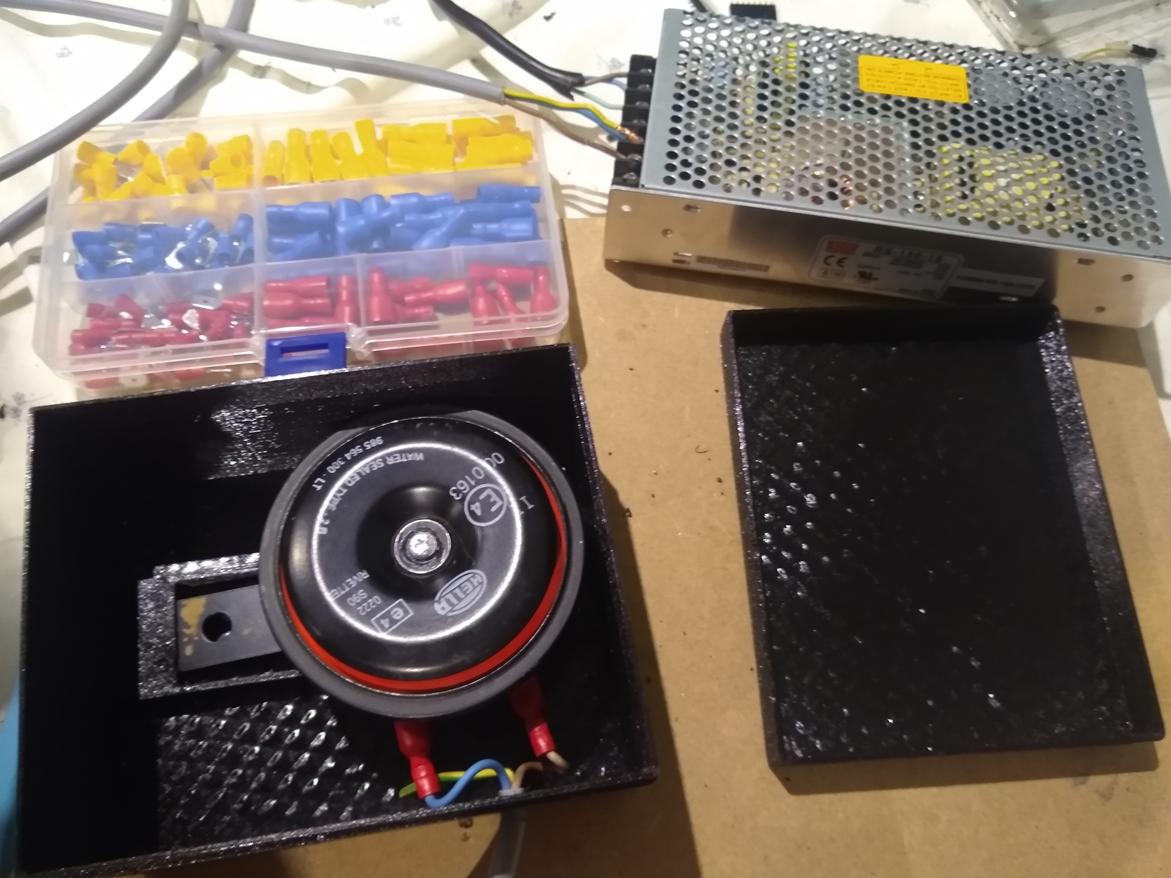
Used components:
Automotive horn, to give an idea about the sound level: it’s the horn of a scooter. You could also go for a double variant.
Power supply providing a voltage between 9-16 V (capable of driving ~40 watt), I still had a 15V, 10A supply lying around so didn’t buy a new one (mine is link this).
Smart switch to control the power supply and control the periodic honking at the moles Example Sonoff S26
Plastic box to shield the horn from dirt. I’ve 3d-printed one, but any box can do.
Power chord
Putting it together
An enclosure was 3d-printed so the claxon is protected and the steel disk remains free to vibrate (and hence produce sound), of course you can just use any other platic box.
Note: just wrapping it in a plastic bag will not be sufficient: if something prevents oscillation of the steel disk, no sound will be produced anymore (ask me how I know …).
In the 3d-printed enclosure, a small hinge was designed to keep the horn in place inside the box. Files for the enclosure can be found here: stl file, openscad file.
I just can’t find the thingiverse source back where I modified this box from :(.
Enclosure
Wiring with matching connectors and power supply was done, et voila: ready to honk. Just don’t test it next to your ears … .
The different components (power supply, horn, platic enclosure, connectors)
Ground works
Installation was tried at different depths under the ground. I had to dig it in at a depth of ca. 80cm before the outside sound was judged low enough to not annoy my neighbours. Sound does travel better in solids than it does in air :).
The wiring and connector was installed downwards so no debris will enter the enclosure by gravity.
Automation
The claxon cannot be turned on cotinuously. So a small automation was created to let it honk for ten seconds every ten minutes.
Since all my other home automations are already using home assistant and the S26 switch flashed with tasmota. I didn’t detail this further.
Result
So far (two weeks after install), the moles didn’t create any new ground constructions in the greater area close to the claxon, I call this a success so far :).
3 - Heating Automation
House heating automation through home assistant and ebus
Automation your damned heaters
I think we all want a more intelligent control over our heaters than what the standard thermostats have to offer. e.g. Automatically turning the heating off when leaving your home, scheduling the heater to turn on sooner in the morning when it’s cold, remotely turning on/off the heating when coming home, … .
Disregarding privacy concerns and long-term servicing for a minute, commercial solutions like Google Nest only seem to support on/off control of the heating. If we want to use proportional/modulated heating for more comfort, at the time of writing, the amount of solutions seems very limited.
Luckily, the open-source world has done a massive amount of work related to home automation and understanding the protocols used by commercial heating systems. Despite all this work, it is a learning curve to find your way through all the different tools / programs and how to use them. When my system ever breaks down I want to have some documentation how I did everything again. So I’ve made some documentation and made it public … .
3.1 - intro
Goal
If your goal is to remove your thermostat completely, that’s not going to happen in this blog.
The posts provide guidance how to add additional intelligence and monitoring to our setup and serve as documentation for myself and others. It’s not a dummy proof step-by-step guide.
Tools
We’ll be using the following hardware and software:
A debian based system ( (old) laptop, tinkerboard, Raspberry pi 3b, …)
Ebus is the communication protocol used by a lot of heating systems, we’ll have to tap into this communication system to help our thermostat become more intelligent.
It’s fair to say without the ebusd software this project would never have happened.
set our requested room temperature through the interface of Home Assistant.
Preparing the host
There is hassbian, hass.io, homme-assistant itself, … as you see, not confusing at all :). I’m using a regular debian based system since at least I know ebusd works in a debian environment. I’m not familiar with docker (hass.io) and its limitations.
A detailed description to setup your host can be found here.
Initial temperature test using Home Assistant
It’s time to get our heater commanded through Home Assistant.
In general it’s good to:
read a few intro’s on Home Assistant before you jump in to it
get Samba up and running so you can edit your home assistant files from your standard working computer (again enough other tutorials can be found)
Concept
We’ll be using python scripts to trigger actions from Home Assistant to ebus(d).
In this way we can focus on making all the ebus related items running in python and we don’t have to deal with the custom Home Assistant syntax. I personally prefer spending time learning python over learning a custom program specific language/syntax.
python scripts
We’ll create a few python scripts to test if we can control our heater from python. On the Pi we will create a new folder python_scripts locate the scripts in /home/homeassistant/.homeassistant/python_scripts.
The script below with the name set_temperature_on.py will set the day and night temperatures to 21C by calling the appropriate ebus commands directly from the command line (making use of the subprocess function). The second part of the script just does an additional check if it was really set correctly.
create the same script with the name set_temperature_off.py where msg2 in the script below has been changed to msg2=15. (Yes, I know this is a stupid way of working and we should give the temperature as an argument to the python script. But for initial testing/debugging this is good enough.)
import subprocess
import time

msg2="21" #setpoint temperature degrees celsius

msg1="ebusctl write -c f37 Hc1DayTemp "
cp = subprocess.run([msg1+msg2],shell=True,stdout=subprocess.PIPE)

msg1="ebusctl write -c f37 Hc1NightTemp "
cp = subprocess.run([msg1+msg2],shell=True,stdout=subprocess.PIPE)

#redundancy check if it is truly set
time.sleep(60)

cp = subprocess.run(["ebusctl read Hc1DayTemp"],shell=True,stdout=subprocess.PIPE)
temp=cp.stdout
if int(float(temp[0:4]))!=int(msg2):
    # if not set correct
    msg1="ebusctl write -c f37 Hc1DayTemp "
    cp = subprocess.run([msg1+msg2],shell=True,stdout=subprocess.PIPE)


cp = subprocess.run(["ebusctl read Hc1NightTemp"],shell=True,stdout=subprocess.PIPE)
temp=cp.stdout
if int(float(temp[0:4]))!=int(msg2):
    # if not set correct
    msg1="ebusctl write -c f37 Hc1NightTemp "
    cp = subprocess.run([msg1+msg2],shell=True,stdout=subprocess.PIPE)
else:
    print("setting correct")
check if the scripts are really working by running the command from the raspberry pi terminal python3 -i set_temperature_on.py
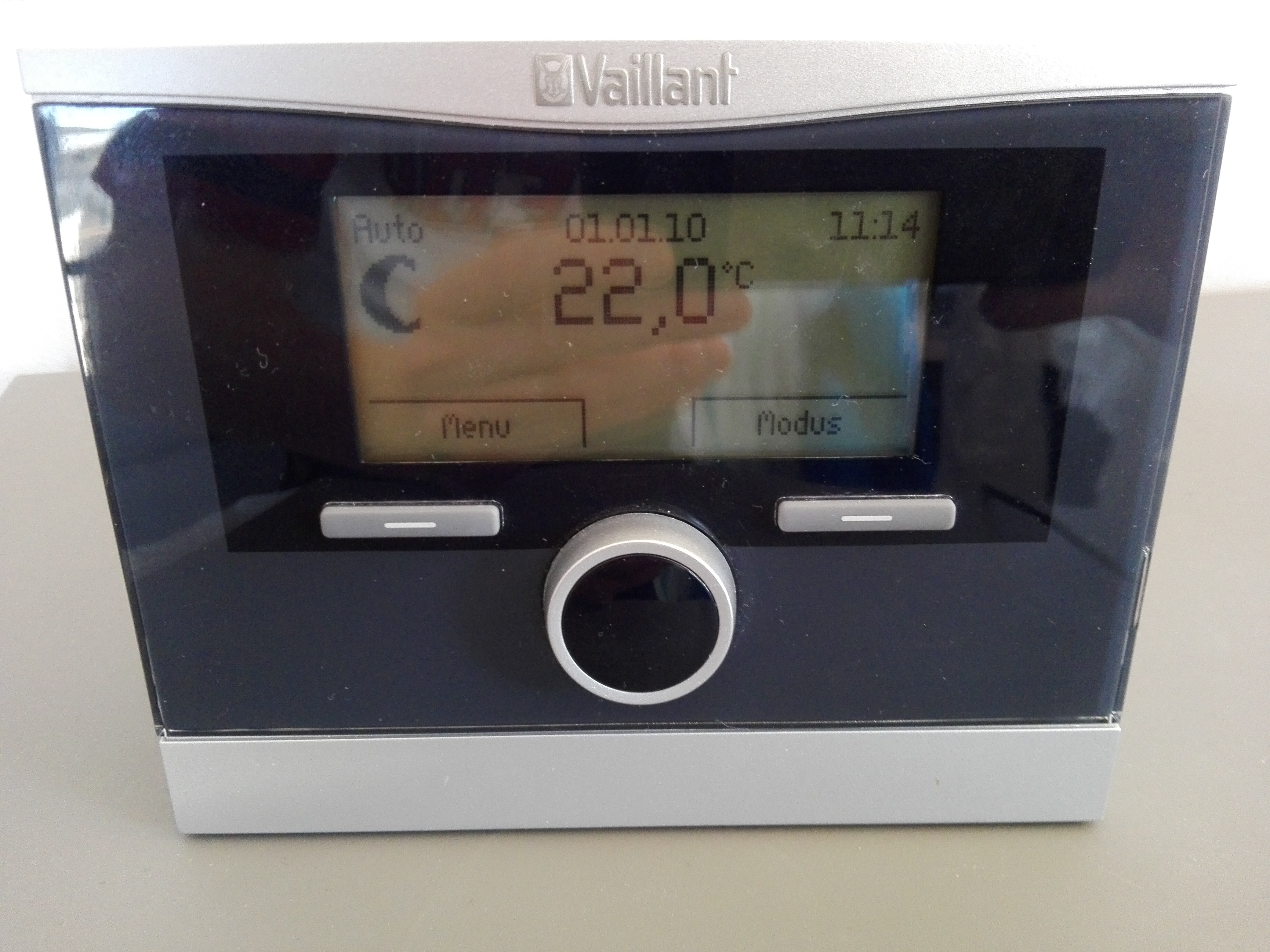
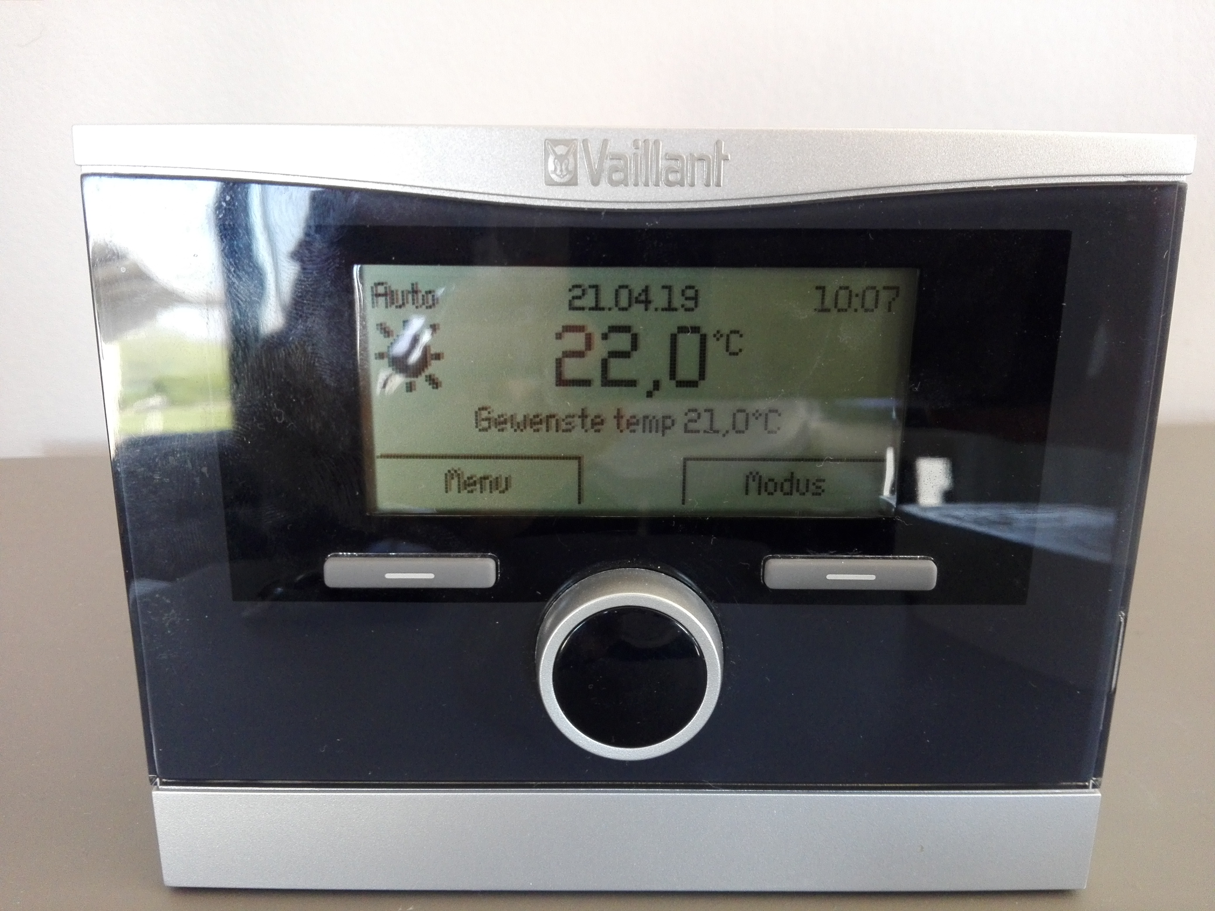
as an additional check, on the thermostat you will see the temperature setting change
Python script has set temperature to 21 degrees!
do the same for the script python3 -i set_temperature_off.py
Now this is working, we’ll link it to Home Assistant.
If you’ve followed Home Assistant intro’s, you know all magic happens in the configuration.yaml file(s).
We’ll be using the shell_command component which basically just executes a script in the terminal / command line of the raspberry.
Add the following into configuration.yaml and reload/reboot home assistant.
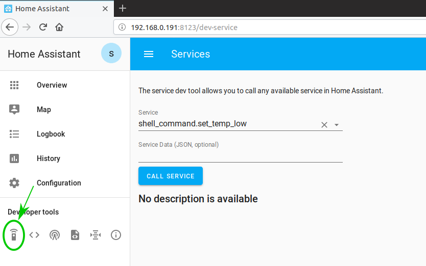
if you select the set_temp_low and set_temp_high and press “call service” the temperature will be set to 15 and 21 degrees :)
Service becomes available in Home Assistant
Clean up method
In the sections above, we’ve demonstrated the basic functionallity of controlling the temperature requests. Next steps are:
to provide the temperature as an argument from Home Assistant to the python script (instead of the hardcoded values from above)
get rid of seperate python scripts for each function (harder to maintain)
make sure not multiple people write at the same moment to the ebus (don’t want to confuse our system)
Adapt python scripts
Starting with the python scripts:
We want to provide the temperature as argument to our python script (have msg2 as an external input in our script)
We’ll use the getopt module in python and parse the arguments to create a temp setpoint,
import getopt

# check if passed options are valid
try:
    options, args = getopt.getopt(sys.argv[1:], 't:',['temperature_setpoint='])
    print(options)
    print(args)
except getopt.GetoptError:
    print("incorrect syntax")
    print("usage: python3 set_temperature.py -t <value>")
    print("default to 12 degrees")
    msg2=12
    sys.exit(2)
for opt, value in options:
    if opt in ('-t','-T','--temperature_setpoint'):
        msg2=value
        print("successful argument")
        print(msg2)
running the script in commandline becomes: python3 /home/homeassistant/.homeassistant/python_scripts/set_temperature.py -t 20.5
User interface
In configuration.yaml, we’ll define three input boxes for setting a temperature (night, day and an additional one for instant change of the heating).
The critical part are the additional {{}} arguments in the shell_command definition. The exact name of the argument you need to find back in the states menu in the user interface.
import subprocess
import time
import getopt
import sys
from ilock import ILock

# check if passed options are valid
try:
    options, args = getopt.getopt(sys.argv[1:], 't:',['temperature_setpoint='])
    print(options)
    print(args)
except getopt.GetoptError:
    print("incorrect syntax")
    print("usage: python3 set_temperature.py -t <value>")
    print("default to 12 degrees")
    msg2=12
    sys.exit(2)
for opt, value in options:
    if opt in ('-t','-T','--temperature_setpoint'):
        msg2=value
        print("successful argument")
        print(msg2)

with ILock('ebus', timeout=200):
	msg1="ebusctl write -c f37 Hc1DayTemp "
	cp = subprocess.run([msg1+msg2],shell=True,stdout=subprocess.PIPE)

	msg1="ebusctl write -c f37 Hc1NightTemp "
	cp = subprocess.run([msg1+msg2],shell=True,stdout=subprocess.PIPE)

	time.sleep(30)

	#check if it is truly set
	cp = subprocess.run(["ebusctl read Hc1DayTemp"],shell=True,stdout=subprocess.PIPE)
	temp=cp.stdout
	if int(float(temp[0:4]))!=int(float(msg2)):
	    # if not set correct
	    msg1="ebusctl write -c f37 Hc1DayTemp "
	    cp = subprocess.run([msg1+msg2],shell=True,stdout=subprocess.PIPE)

	cp = subprocess.run(["ebusctl read Hc1NightTemp"],shell=True,stdout=subprocess.PIPE)
	temp=cp.stdout
	if int(float(temp[0:4]))!=int(float(msg2)):
	    # if not set correct
	    msg1="ebusctl write -c f37 Hc1NightTemp "
	    cp = subprocess.run([msg1+msg2],shell=True,stdout=subprocess.PIPE)
	else:
	    print("setting correct")
3.3 - Setup hardware and ebus
Intro
In this part we’ll connect to the communication bus of the heater and read / write some parameters by manually commanding them via a debian based system (tinkerboard, raspberry, laptop, …).
Hardware
Ebus adapter
We need an ebus adapter for the raspberry to interface with our heater. I’m not going to write down all the details, since I can just refer to them:
I’m using the base board version 2.2, there might be better options to use directly with a raspberry pi. But when I ordered, it looked like the most flexible solution.
Adapter was ordered on the fhem forum. They will send you a pcb with a set of components, you have to solder yourself (or pay a bit extra): https://forum.fhem.de/index.php/topic,93190.msg857894.html#msg857894. If you’ve read the first link you will also know there are commercial options in case you don’t want this.
Put it in a box so there is no chance on touching electrical connections etc. .
You could consider placing the adapter inside the heater (plenty of space), I just didn’t want to put custom electronics inside … .
ebus adapter v2.2
Attention!!
Connecting the ebus adapter over USB to your host, is not reliable over longer periods of time! I’ve wasted way too much time with an unreliable home automation because of this. Connecting the adapter to a wemos, seems the more reliable route.
Use a 32Gb size SD card (recommended by Home Assistant).
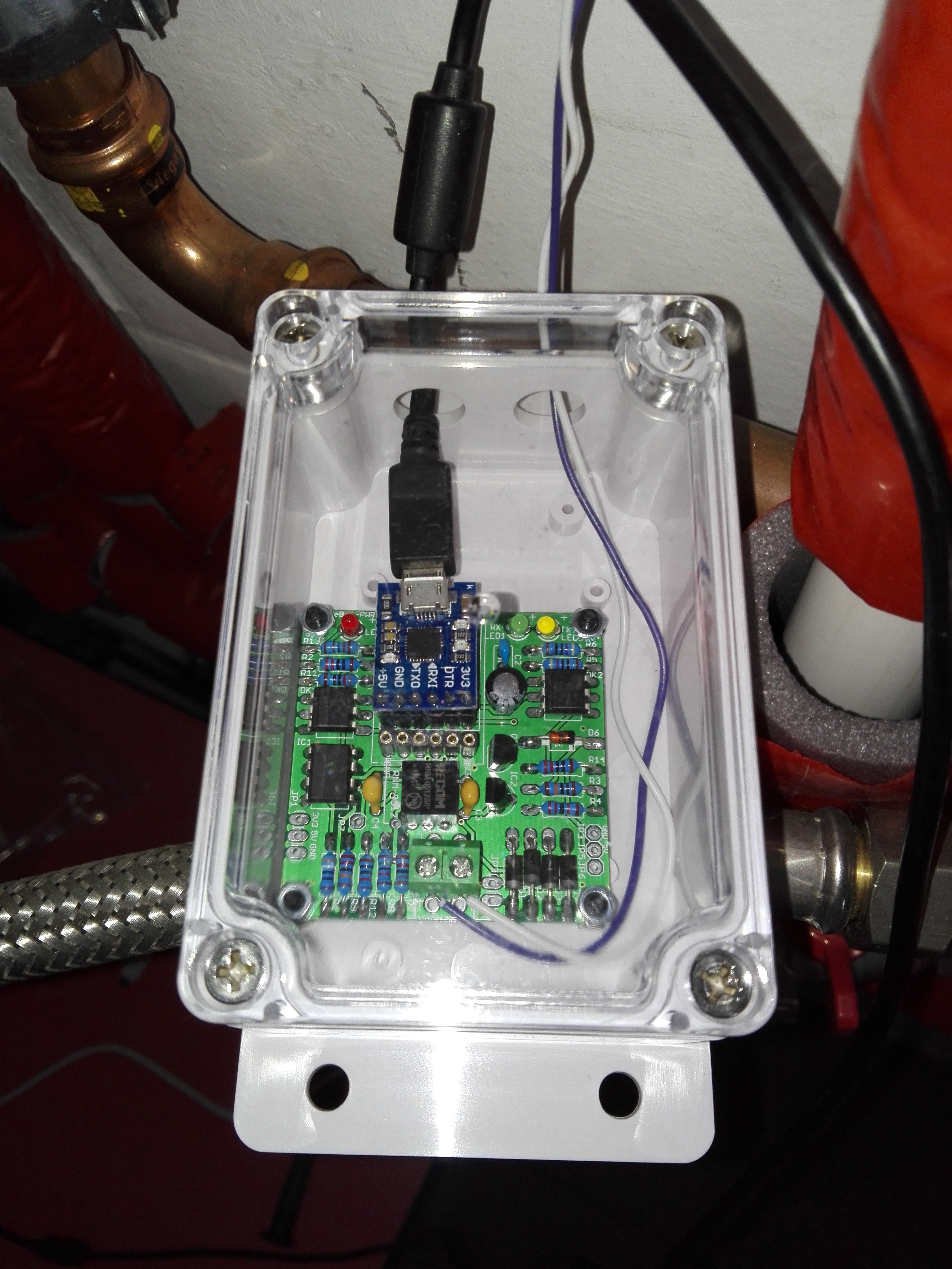
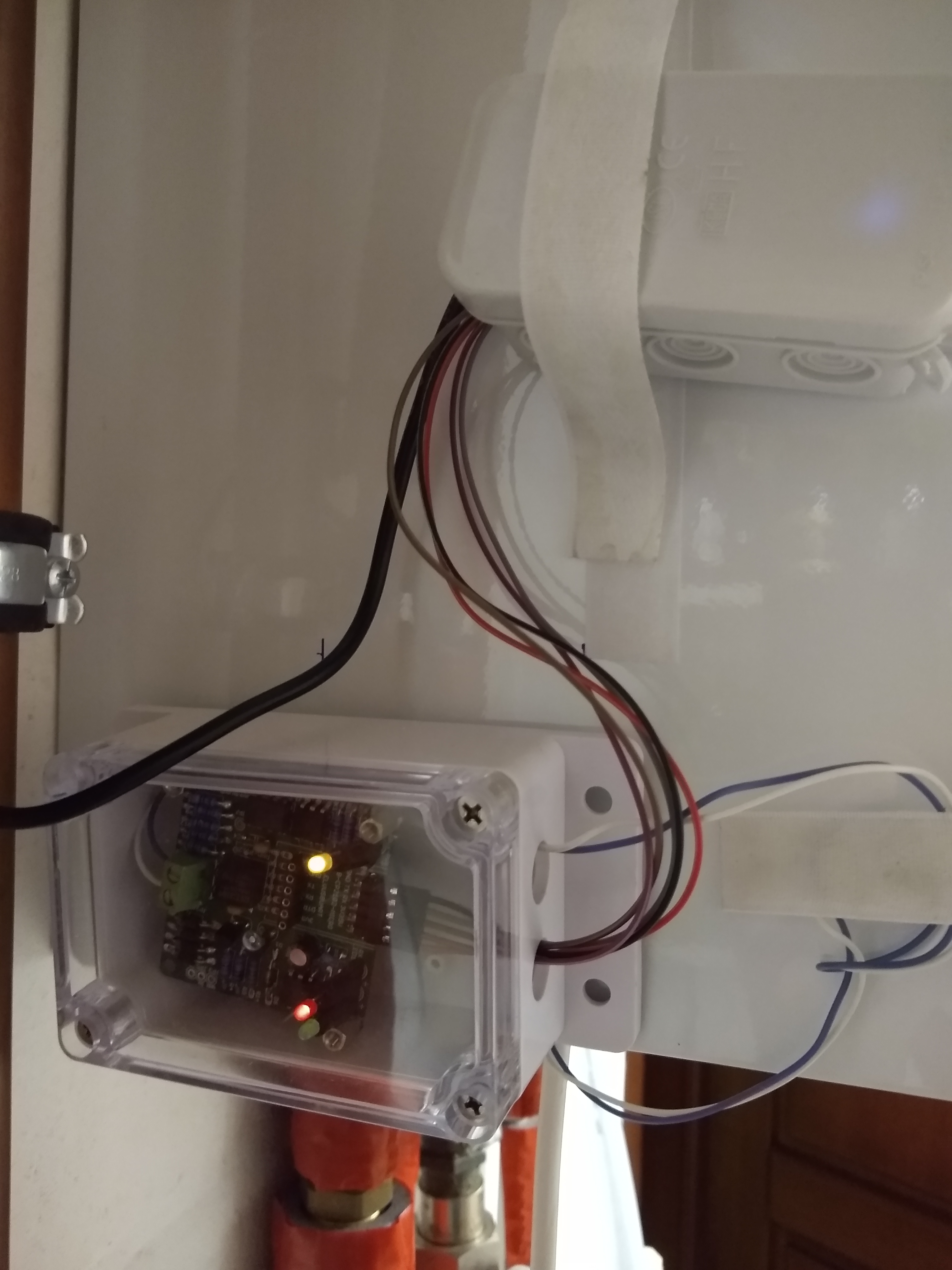
My setup
Wemos mini D1 and ebus adapter mounted on heater
Wemos mini D1 and ebus-adapter (without uart interface) are mounted against the heater by using velco strips
The white and purple wire are the ebus, they are connected inside the heater (ebus protocol has no polarity, so you can swap the wires)
ebus-adapter is connected through five wires as described here
Software
Software Wemos D1 mini
A special software is created by john30, the procedure to start using it is described on his github page.
There is not much too add here.
ebusd
First install the ebus related software on your system running your home automation, see the ebus section in the installation guide.
If this is done, adapt your ebus configuration to match your wemos settings:
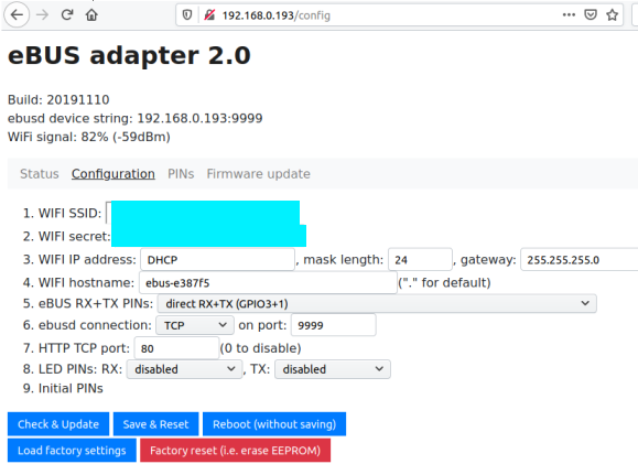
Check the settings in the interface of the wemos / ebus adapter, the ebusd device string is what you’ll need in the next step.
Interface when browsing to wemos D1 mini
adapt the ebus configuration on your host, as described in the following steps:
cd /etc/default
sudo nano ebusd
Adapt the EBUSD_OPTS in the file, so you get something like the example below. (Pending your internet connection / hardware you might have to play with the latency parameters.)
# /etc/default/ebusd:
# config file for ebusd service.

# Options to pass to ebusd (run "ebusd -?" for more info):
#EBUSD_OPTS="--scanconfig"
EBUSD_OPTS="-d 192.168.0.193:9999 -l /var/log/ebusd.log --scanconfig --latency=100000 --address=01"
# MULTIPLE EBUSD INSTANCES WITH SYSV
# In order to run multiple ebusd instances on a SysV enabled system, simply
# define several EBUSD_OPTS with a unique suffix for each. Recommended is to
....
Do a restart of the ebusd and check its status:
sudo systemctl restart ebusd
sudo systemctl status ebusd
The output should look like this:
● ebusd.service - ebusd, the daemon for communication with eBUS heating systems.
   Loaded: loaded (/lib/systemd/system/ebusd.service; enabled; vendor preset: enabled)
   Active: active (running) since Sat 2019-12-21 16:45:54 UTC; 56min ago
  Process: 3221 ExecStart=/usr/bin/ebusd $EBUSD_OPTS (code=exited, status=0/SUCCESS)
 Main PID: 3222 (ebusd)
    Tasks: 4 (limit: 4749)
   Memory: 1.5M
   CGroup: /system.slice/ebusd.service
           └─3222 /usr/bin/ebusd -d 192.168.0.193:9999 -l /var/log/ebusd.log --scanconfig --latency=100000 --address=01

Dec 21 16:45:54 tinkerboard systemd[1]: Starting ebusd, the daemon for communication with eBUS heating systems....
Dec 21 16:45:54 tinkerboard systemd[1]: Started ebusd, the daemon for communication with eBUS heating systems..
check if your heating system is identified by running ebusctl info:
xxx@tinkerboard:~$ ebusctl info
version: ebusd 3.4.v3.3-51-g57eae05
update check: revision v3.4 available
signal: acquired
symbol rate: 42
max symbol rate: 102
min arbitration micros: 20
max arbitration micros: 177
min symbol latency: 6
max symbol latency: 80
reconnects: 0
masters: 3
messages: 345
conditional: 2
poll: 0
update: 9
address 01: master #6, ebusd
address 03: master #11
address 06: slave #6, ebusd
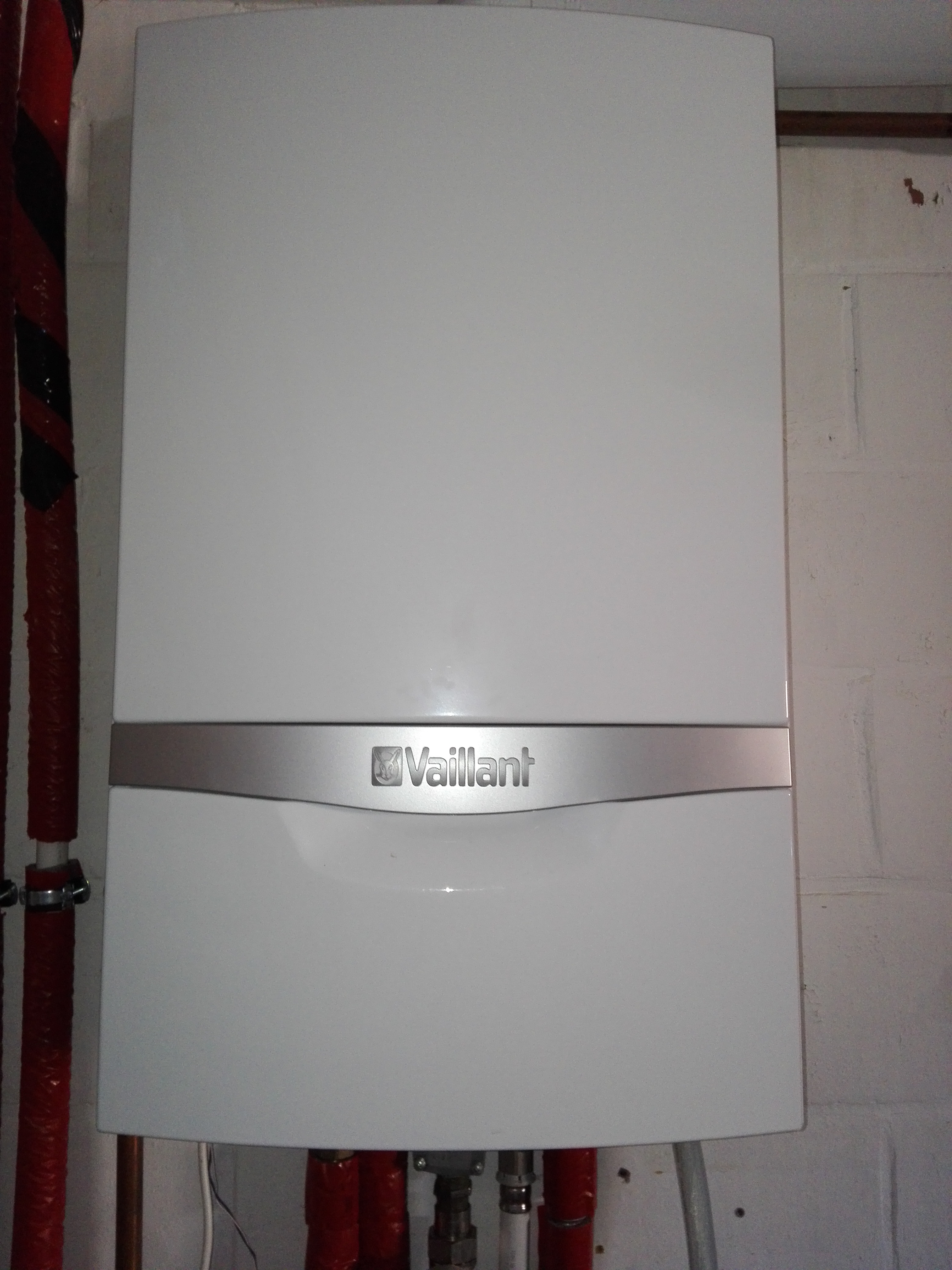
address 08: slave #11, scanned "MF=Vaillant;ID=BAI00;SW=0202;HW=9602", loaded "vaillant/bai.0010015600.inc" ([HW=9602]), "vaillant/08.bai.csv"
address 10: master #2
address 15: slave #2, scanned "MF=Vaillant;ID=F3700;SW=0114;HW=6102", loaded "vaillant/15.f37.csv"
Query some commands to see if everything is working as expected.
Useful commands to debug can be tail -30 /var/log/ebusd.log, this to see what ebus has been written to the log file configured in EBUSD_OPTS.
3.4 - Read information
Intro
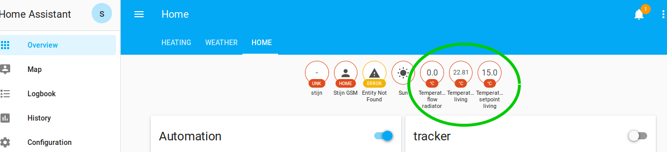
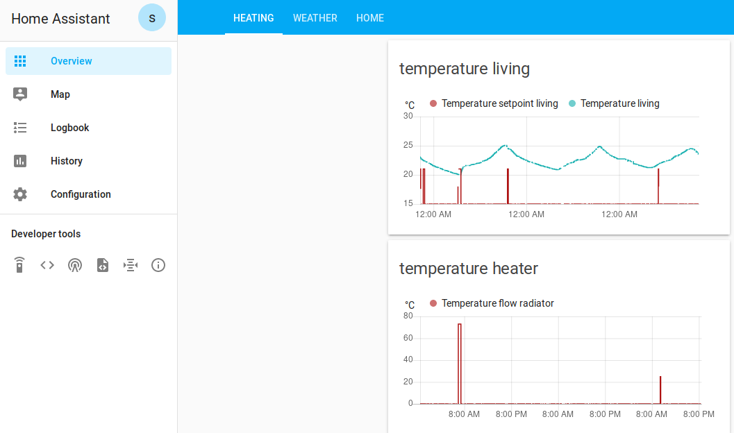
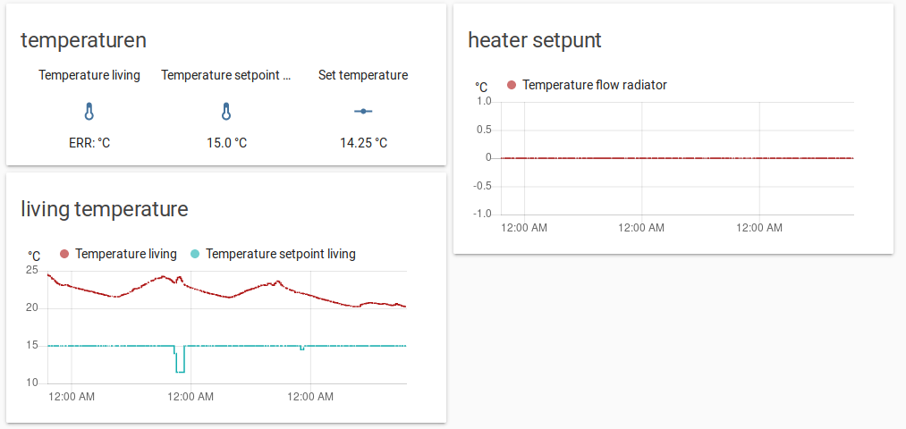
In this part we’ll read parameters from our heater through the interface of Home Assistant and plot them in the UI.
Concept
We’ll be (mis)using the mqtt protocol to send messages from the ebusd program to Home Assistant. This sending of messages will be done in a python script.
Again: in this way we can focus on making all the ebus related items running in python and we don’t have to deal with a custom Home Assistant syntax. I personally prefer spending time learning python over learning a custom program specific language/syntax.
Python script
script below:
queries the ebus for certain parameters (three temperatures in this example)
broadcasts them as an mqtt message, pay attention the messages generated in the python scripts (e.g. sensor/thermostat/temperature) match with the state_topic defined in the sensors (see next section)
store the script again in /home/homeassistant/.homeassistant/python_scripts/
Add the following mqtt sensors to configuration.yaml. This contains a username and password for the mqtt configuration (stored in secrets.yaml), for initial debugging you could consider removing username and password.
We’ll create a shell_command to be able to call the python script above to read out the parameters on the ebus, we’ll add a third item called read_ebus (readtime_thermostat.py is the script mentioned above).
Now we will use a first automation to trigger a periodic reading of the ebus (if you don’t want to do this in Home Assistant you could do this in python as well). Here we’ll trigger a new reading every 7 minutes.
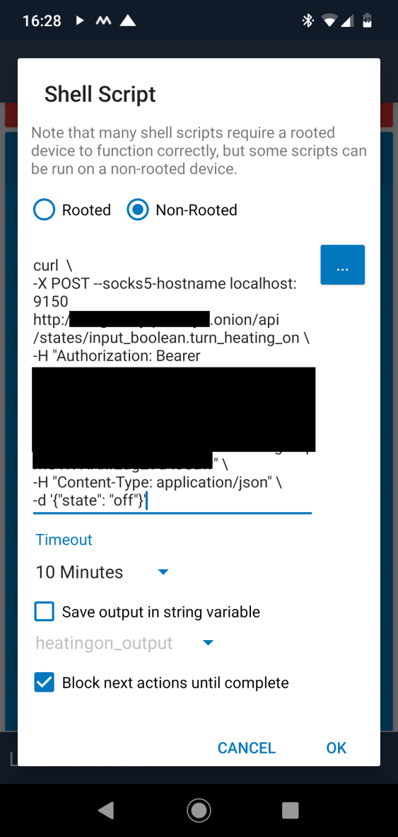
This is the continuation of HomeAssistant Tor. Here we’ll create a macro to automatically turn our heating on/off from an Android phone. The end result is something which only requires two / three pushes on a button on your android phone to turn on my heating.
It works when being connected to a mobile network as well as a wifi network.
Method and tools
Macrodroid: Android app used for creating the macro. It’s free and can do everything we need.
Test your shell script and play with the “state” attribute, you should see the turn_heating_on change accordingly (“off”/“on”)
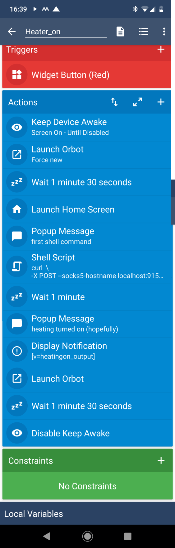
Incorporate in larger macro
Create a larger macro which starts and stops Orbot automatically.
Since my home automation assumes a change from “off” to “on”, the turn_heating_on will be first put “off” and then put to “on”
Macrodroid macro
The end result is, I need two/three pushes on the screen to turn my heating on:
First push: start the macro
Second push: when the orbot screen launches, push the big onion to connect to the tor network
Optional third push: when the orbot screen launches for the second time, disconnect from the tor network
3.6 - Additonal electric heater
Intro
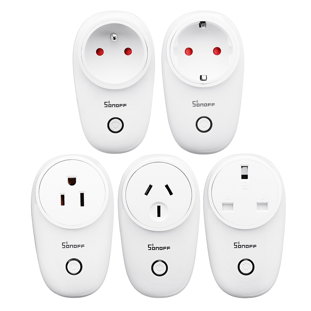
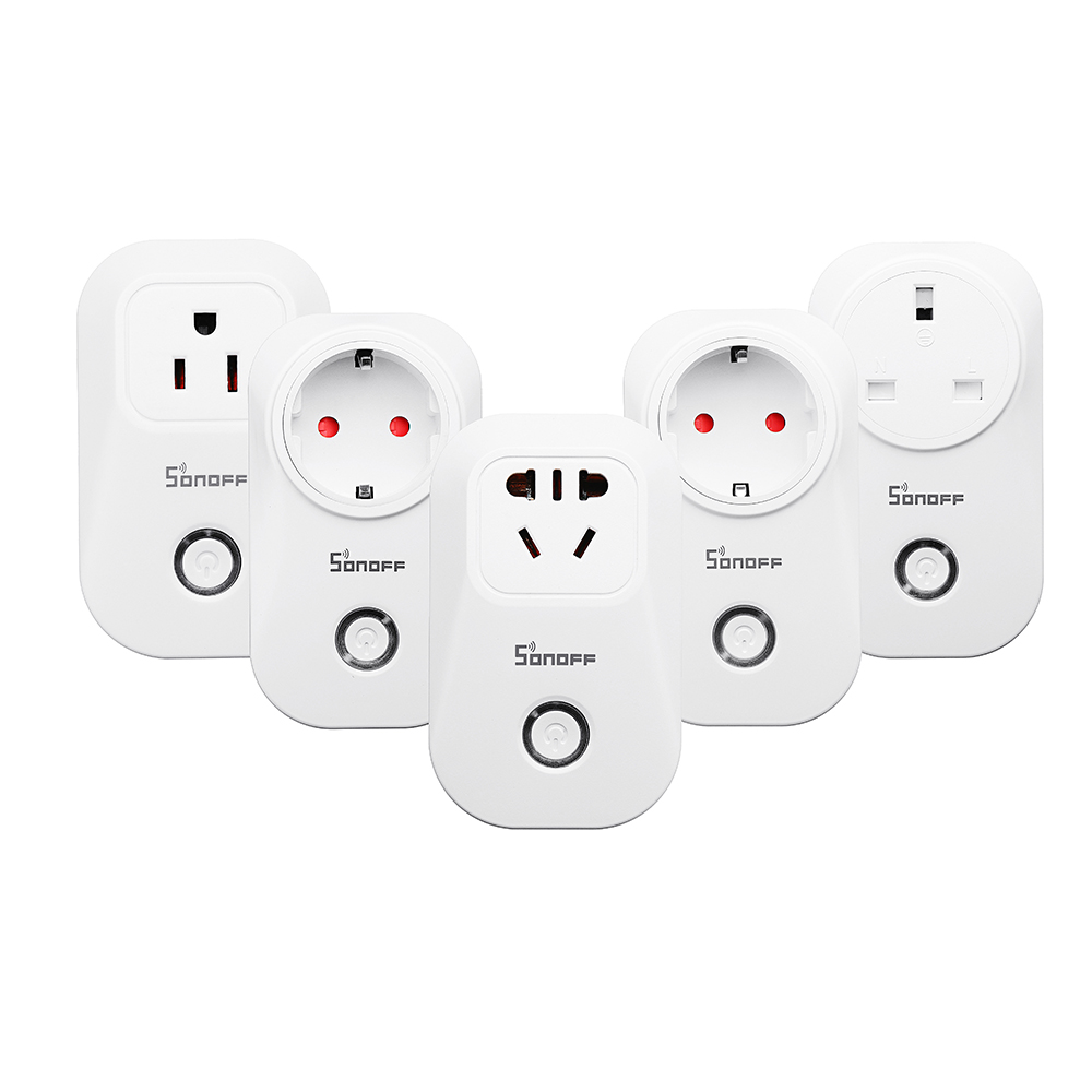
We’ll be using one of the sonoff devices to turn on/off a wall-plugged electric heater. These devices are pretty cheap but since we’ll be hacking into them, use at your own risk.
The sonoff S20 is more hackerfriendly compared to the S26 (from soldering standpoint). But once it’s done, the S26 is more compact and looks slick :). I’ve used both in the meantime (and I’m not a soldering guru by far).
Once this is done, MQTT messages will be used to control and report the status through the interface of Home Assistant
Configure MQTT Tasmota
First, flash the Tasmota software.
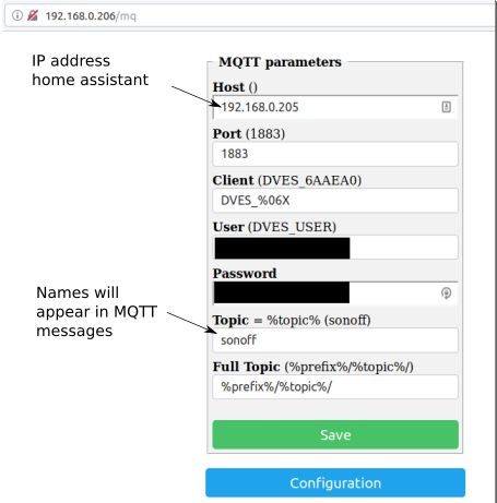
Then browse to the ip-address of your sonoff device and click further to do some limited MQTT configuration. Here you can define the names / passwords / username of your MQTT topics (see screenshot below). The full name of the MQTT can be double checked in http://IP_ADDRESS_OF_YOUR_SONOFF/in.
MQTT configuration in Tasmota
The MQTT methods in the Tasmota software are very well documented (a bit overwhelming at first):
Two MQTT topics will be used for this application:
one to report the status
one to send the commands (this one doesn’t need additional configuration)
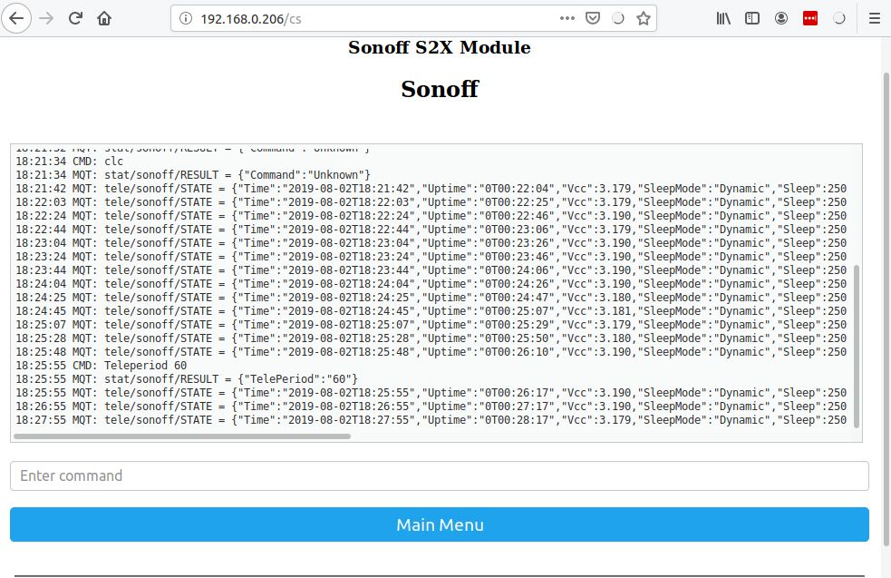
To monitor the status of the device, the tele-messages - continuously broadcasted by Tasmota - will be used. The update rate of the tele-message can be set with the TelePeriod command (see screenshot below).
Configure update rate of the tele-message to 60 seconds
Home assistant
First check if the messages truly arrive on the host, by listening to them from the terminal on the host:
Now, define a binary sensor in configuration.yaml to monitor the on/off status of the device. Here the value_template needs to be used to filter the specific message we want (here on/off of the device).
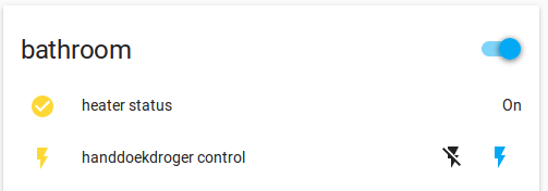
et voila, one can command and read the status of the sonoff device through Home Assitant:
(of course there is a delay of maximum 60s in the status reporting due to the usage of the tele-message.)
MQTT configuration in Tasmota
3.7 - Link with house alarm
Intro
I’ve let a relay install during yearly maintenance of my burglar alarm, this allows me to tell me when the alarm is turned on or off. This makes life for presence detection significantly more simple :).
We’ll use MQTT to send status of alarm to Home Assistant.
Troubleshooting
The connection of a Wemos D1 with Arduino IDE seems to be junk (the arduino IDE part). We need to use esptool instead
pip3 install esptool.
Location
Can be updated over the air (ota), so you only have to fysically connect it once (in theory at least, if everything uploads correctly)
4 - e-paper display
e-paper display linked with home assistant
Double e-paper display used to display various information and pictures, integrated with Home Assistant
E-paper display linked with Home Assistant
I wanted a display which:
does not consume (a lot of) electricity
is linked with home-assistant, so I can get useful updates pending the moment of the day
can display interesting photos, when I don’t want to know the status of my house / surroundings :)
doesn’t cost an arm and a leg
The result of my tinkering can be seen in the picture above.
I’ve used two 7.5 inch e-paper displays and incorporated them into a picture frame. The reason for two dislays is mainly because larger e-papers just become very expensive. Obviously you don’t need two, if you don’t want to… .
4.1 - Display Intro
Concept
In the following posts, the different parts of the display are explained in more detail:
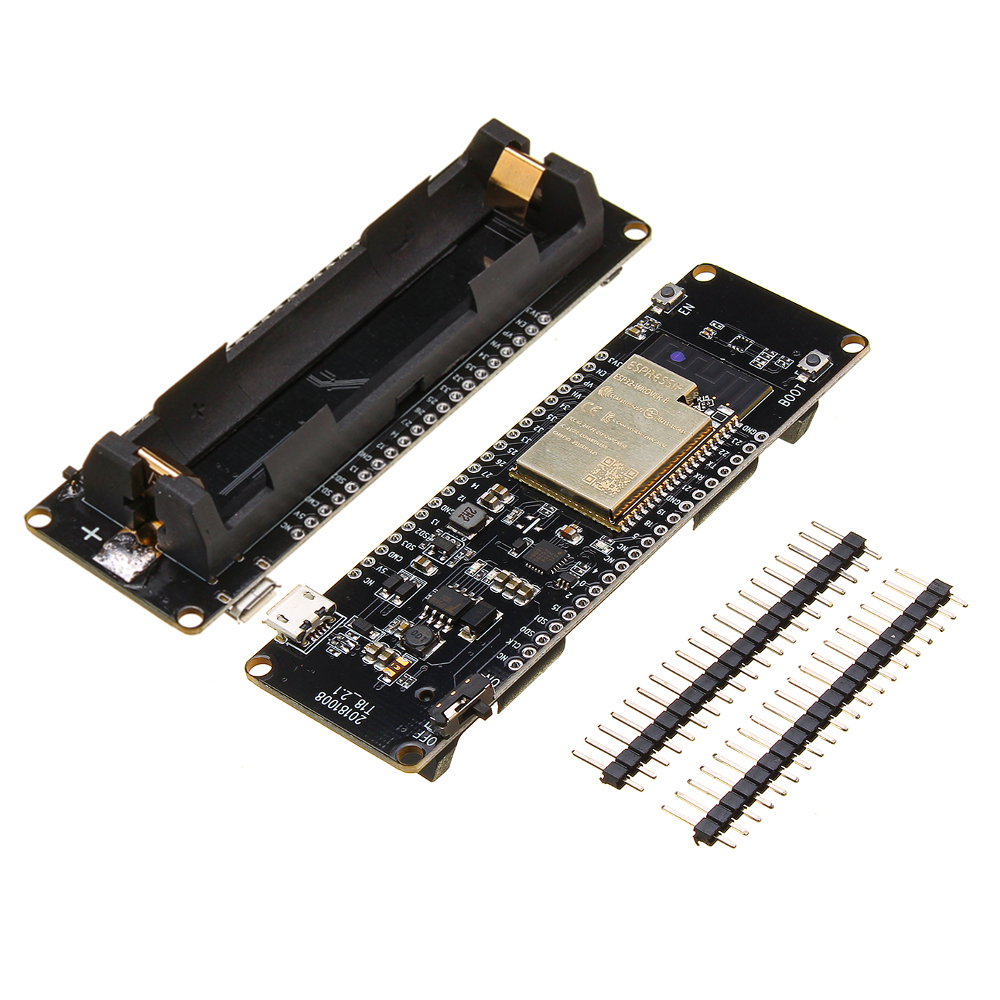
I should not have bought an ESP32 board including an 18650 battery: this types of batteries is barely available in Europe + if I want it battery operated I can just attach a powerbank, there is more than enough space in the picture frame.
add description of construction
4.2 - Concept
Intro
This part sketches the entire flow. I’ve changed my method a few times during the creation of this. Mainly because I just stumble upon things in the home assistant documentation, rather than actually finding something when I need it :).
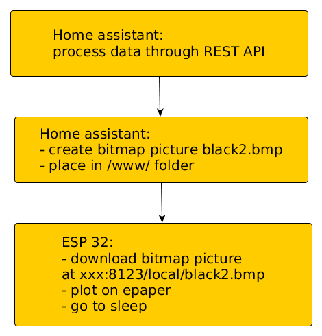
Different steps
Sequence to get home assistant content on e-paper
Relevant references to documentation (I want to find it back myself ;):
I’m using a debian version running home assistant (without docker etc.), I have not checked if anything should change when using hassio and other variants
the REST API, would allow to do everything on the esp32, but I didn’t go that route … .
4.3 - Actuate display using ESP32
Intro
In this part, a figure, living on the Home Assistant server, will be displayed on a 7.5 inch e-paper using an ESP32-based board.
The SPI interface of the ESP32 will be used to control the display.
The pins of SPI quickly get confusing:
Names of the different interfaces of SPI aren’t very consistently used (MOSI, SPI D, SD0, SS, CS, SCK, CLK, SD1, … ) + you have to pay attention to the difference between IO pins and GPIO pins in the ESP32 datasheet.
The ports labeled on the ESP-board with clk, SD0, SD1, … are linked to an SPI bus. But one only used to flash the device, not used for communication with external devices … .
In the ESP32-wrover datasheet, it can be found two SPI busses are available for external communication: VSPI and HSPI.
Below, the overview is provided to which pins these two busses correspond with. The last column is mainly added to be able to check if custom esp32 boards (like this one) also respect the GPIO labels marked on the board. (The esp32 feet are still large enough to check with a multi-meter.)
VSPI
GPIO (pin label)
Name ESP32-wrover chip
No. ESP32 Chip
MOSI
23
VSPI D
37
MISO
19
VSPI Q
31
SCK
18
VSPI CLK
30
SS
5
VSPI CS
29
HSPI:
HSPI
GPIO (pin number board)
Name ESP32-wrover chip
No. ESP32 Chip
MOSI
13
HSPI D
16
MISO
12
HSPI Q
14
SCK
14
HSPI CLK
13
SS
15
HSPI CS
23
For the BUSY, reset and DC pin, any suitable DIO can be selected. This is how it looks in my configuration / script for VSPI:
static const uint8_t EPD_BUSY = 4;  // to EPD BUSY
static const uint8_t EPD_CS   = 5;  // to EPD CS
static const uint8_t EPD_RST  = 21; // to EPD RST
static const uint8_t EPD_DC   = 22; // to EPD DC
static const uint8_t EPD_SCK  = 18; // to EPD CLK
static const uint8_t EPD_MISO = 19; // Master-In Slave-Out not used, as no data from display
static const uint8_t EPD_MOSI = 23; // to EPD DIN
Esp 32: the code
The great GxEPD2 library will be used for drawing on the e-paper display.
A good example to verify if your pinout is correct and libraries are installed correctly, is to use this implementation: Weather display
For our purposes the default example in the library - GxEPD2_WiFi_Example.ino - will be modified to fit our purposes.
The main challenge was to make it download an image from a local website (home assistant at http://192.168.0.205:8123/local/black2.bmp ).
The resulting script can be found here, if you want to test it out:
A Credentials.h file is expected which contains your WiFi settings
Pay attention to set the SleepDuration, WakeupTime, SleepTime, … in the script when the system should remain awake
Of course, change 192.168.0.205:8123 to your own home assistant settings
Others
if you want to play around with displaying any image, I use ImageMagick to convert images to bitmaps consisting of 3D arrays (and not 4D) with the command:
This is the part to generate the content out of home assistant and display it on our e-paper.
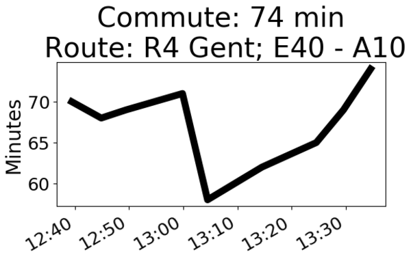
As an example I will display the expected commute time to work.
Python scripts being defined as a shell_command in configuration.yaml will be used. A simple automation to trigger the python script will be used.
Basis of script
We want to make a plot that tells us the expected time of our commute with a graph of the last hour, to see how the time is trending.
The component waze travel time, will be used to estimate our commuting time (with the name sensor.commute). Setting this up is not described in further detail.
You should create a www directory in your configuration folder
Note: To get the data out of home assistant, I’ve explored a few routes. Using hass-python script for interfacing with home assistant, scripts that would operate on home-assistant_v2.db, … until I’ve stumbled upon the Home Assistant: REST API. After this discovery, I don’t know why I should use anything else to capture data. Since this can be accessed from anywhere on the network (and makes debugging easy).
REST API
The documentation from the REST API, describes how to obtain a long term token. This needs to be filled in the hearders file (the xxx location).
#location where figure will be stored
path="/home/homeassistant/.homeassistant/www"
os.chdir(path)

# e-paper display size
width_displ=640
height_displ=384
dpi=100;

headers = {
    'Authorization': 'Bearer xxx,
    'content-type': 'application/json',
}
address_hass='192.168.0.205'
Getting timezones
All data gets stored with UTC timestamps. We want to convert our data to the local timezone.
Obtaining the timezone can be done by requesting the /api/config:
# get timezone to convert to local time, since database attributes are in UTC time
url='http://'+address_hass+':8123/api/config'
response = get(url, headers=headers)
temp=response.text
readable_json=json.loads(temp)
time_zone=readable_json['time_zone']
tz = timezone(time_zone)
Get sensor history
Here the data from our sensor will be obtained, by default the history of 1 day is provided. The data will be stored in numpy arrays and will be immediately converted to the local timezone.
entity_id='sensor.commute'

# this downloads history of the last day
url='http://'+address_hass+':8123/api/history/period'+'?filter_entity_id='+entity_id

response = get(url, headers=headers)
temp=response.text
temp=temp[1:len(temp)-1]
readable_json=json.loads(temp)

time_array= np.array([])
state_array=np.array([])
for i in readable_json:
    time_update=datetime.strptime(i['last_updated'],'%Y-%m-%dT%H:%M:%S.%f%z')
    time_array=np.append(time_array, time_update.astimezone(tz))
    state_array=np.append(state_array,float(i['state']))
Create bitmap file
At last, a plot from the data within the last hour will be created,
the x-axis will be plotted containing hours and minutes
# only plot data from last hour
time_treshold=time_array[-1]-timedelta(hours=1)
idx=time_array>time_treshold

last_info=readable_json[-1]
last_attr=last_info['attributes']

fig=plt.figure(num=None, figsize=(int(width_displ/dpi), int(height_displ/dpi)), dpi=dpi, facecolor='w', edgecolor='k')

plt.plot(time_array[idx],state_array[idx],linewidth=7.0,c='k')
plt.ylabel('Minutes',fontsize=20)
plt.xticks(fontsize=18)
plt.yticks(fontsize=18)
ax = plt.gca()
ax.yaxis.set_major_formatter(FormatStrFormatter('%.0f'))

plt.title('Commute: '+format(state_array[-1],'.0f')+' min'+'\n '+'Route: '+last_attr['route'],fontsize=28)

xformatter = DateFormatter('%H:%M')
plt.gcf().axes[0].xaxis.set_major_formatter(xformatter)
plt.gcf().autofmt_xdate()

fig.savefig('plot.png',bbox_inches='tight',dpi=dpi)
Example, generated figure:
Example bitmap
Testing the python script
ssh to the home assistant server (raspberry pi)
sudo su -s /bin/bash homeassistant
cd /home/homeassistant/.homeassistant/python_scripts/
python3 db_plotter.py
As a next step we will add options to the python script, so we can command different options through automations in home assistant.
# check if passed options are valid
try:
    options, args = getopt.getopt(sys.argv[1:], 's:',['selection='])
    # print(options)
    # print(args)
except getopt.GetoptError:
    print("incorrect syntax")
    print("usage: python3 db_plotter.py -s <value>")
    print("default to option 1")
    display_option=1
    sys.exit(2)
for opt, value in options:
    if opt in ('-s','-S','--selection'):
        display_option=int(value)
        print("successful argument")
        print(display_option)
The whole script, created above will be moved to an if-else construction
if display_option==2:
    entity_id='sensor.commute'
    ....
Now we need to test the script by running: python3 db_plotter.py -s 2.0
Configuration.yaml
Define the script as a shell command with the option to give different arguments with it, contained in a dummy variable (dummy_epaper).
In this part, the esp32 software will be extended to control two displays.
The described solution mainly comes because of the great support from the creator of gxEPD2, so credits to him.
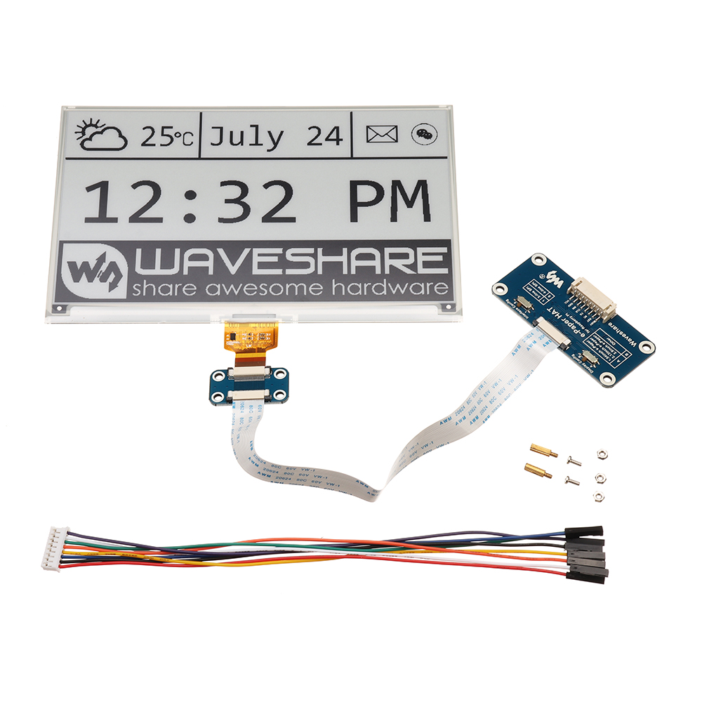
Hardware struggles
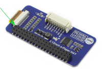
The used 7.5 inch display, comes with an e-Paper Driver HAT.
When connecting it as intended - 3.3V of this ESP32 connected to the 3.3 V of the e-paper HAT - it turns out very unreliable.
It becomes more unreliable when combining more than one e-paper to the display (or it can be my cognitive bias).
The solution is to bypass the voltage converter and directly connect the 3.3V from the ESP32 according the picture below (see scematics):
Alternative 3.3V connection
Software ESP32
SPI
One common SPI is used for both displays; the busy, reset and CS pin are separate pins for each display.
(Using two different SPI’s for both displays, was too much work to make it work.)
#define ENABLE_GxEPD2_GFX 1
#include <GxEPD2_BW.h>

//SPI pins, common for both displays
static const uint8_t EPD_DC   = 22; // to EPD DC
static const uint8_t EPD_SCK  = 18; // to EPD CLK
static const uint8_t EPD_MISO = 19; // Master-In Slave-Out not used, as no data from display
static const uint8_t EPD_MOSI = 23; // to EPD DIN

// display two:
static const uint8_t EPD_BUSY2 = 4;  // to EPD BUSY
static const uint8_t EPD_CS2   = 5;  // to EPD CS
static const uint8_t EPD_RST2  = 21; // to EPD RST
GxEPD2_BW<GxEPD2_750, GxEPD2_750::HEIGHT> display2(GxEPD2_750(/*CS=*/ EPD_CS2, /*DC=*/ EPD_DC, /*RST=*/ EPD_RST2, /*BUSY=*/ EPD_BUSY2));   // B/W display

//display one:
static const uint8_t EPD_BUSY1 = 25;  // to EPD BUSY
static const uint8_t EPD_RST1  = 34; // to EPD RST
static const uint8_t EPD_CS1   = 15;  // to EPD CS
GxEPD2_BW<GxEPD2_750, GxEPD2_750::HEIGHT> display1(GxEPD2_750(/*CS=*/ EPD_CS1, /*DC=*/ EPD_DC, /*RST=*/ EPD_RST1, /*BUSY=*/ EPD_BUSY1));   // B/W display
Displaying
Two images are downloaded now, one for each display: black1.bmp and black2.bmp
Don’t we all want to monitor our home remotely (i.e. when not connected to our local network), turn on the heating on or off if we change our plans, check if everything is going well with our created home automation, etc.
What we want:
a secure method that has limited chance of being hacked
no usage of a cloud service (it’s my data :), it should still work if the company stops existing or a server is down)
preferably free
In this section we’ll use tor to access home assistant remotely and connect to it from our mobile phone (through mobile internet).
Read more about Tor Hidden Services.
Installation
I’m using a debian based system with home assistant running in a virtual (python) environment, as described here.
The documentation to setup tor is here: homeassistant tor.
However, for debian 10 (buster), this isn’t entirely correct anymore.
The ‘HiddenServiceVersion 2’, needs to be added to the torrc configration. All the other steps are still relevant.
As described in homeassistant tor, one need to install Orbot and Orfox (Tor browser).
Configuring Orbot
Use the result obtained by executing $ sudo more /var/lib/tor/homeassistant/hostname, you will obtain something like xxxxx.onion xx....xx.
Edit the torrc file in Orbot –> Settings –> Torrc Custom Config. Fill in: HidServAuth xxxxx.onion xx....xx
One additional step I had to, is to go to Orbot –> Settings –> Tor SOCKS and add port 9150. This to avoid getting a refused connection because of proxy servers.
Home Assistant
The configuration.yaml file should have type: homeassistant to be able to access it remotely.
In my case when connected from the local internet (not through tor), I’m automatically logged in.
If successful, start up the Tor Browser and browse to your xxxxx.onion address. You should see your homeassistant login screen.
Create a bookmark with your .onion address. It’s hard to know it by hard :).
click “Home Assistant Local”
type in your home assistant username and password
and you have your usual interface screen :)
Create a macro
Of course we are all lazy and don’t want to start up Orbot, launch the browser, login to homeassistant, and change our settings.
Here is an example on how to create a macro on an android phone to turn on your heating: link.
5.2 - Setup debian system
Intro
This page is to document the steps starting from a fresh linux install and setting up homeassistant, mqtt and ebusd.
It starts with a fresh install of a debian buster based OS. The guide works on crunchbangplusplus, installed on an (old) laptop with i386 processor; works on armbian running on a tinkerboard.
Quite some additional python and other packages are specific for my installation, they can be left out to suit your needs.
Remote access
To make life easy and not be close to your machine running home assistant:
ssh into the remote machine
sudo apt-get install tmux
start tmux by typing tmux
execute your commands in the started tmux session
leave/detach the tmux session by typing Ctrl+b and then d
If you connect again after being disconnected, type tmux attach
Install home assistant
This one mainly follows the steps outlined on the home assistant website to install Home Assistant in a virtual environment.
First prepare the list of repositories in crunchbangplusplus:
add a line to your /etc/apt/sources.list: deb http://ftp.de.debian.org/debian buster main
Due to some specific installation issues with the 0.100 version, this one had to be installed manually: https://pypi.org/project/home-assistant-frontend/
additional python packages (your own judgement if you need them):
Check if any error messages pop up in the command window. If so, try to resolve them.
Brows to http://ip_address:8123, to see if you can access. Setup an account.
Folder settings
Exit from the virtual environment to set some folder settings.
I copy my yaml and python files through FileZilla, which requires to change the read/write settings.
Maybe there are other solutions … .
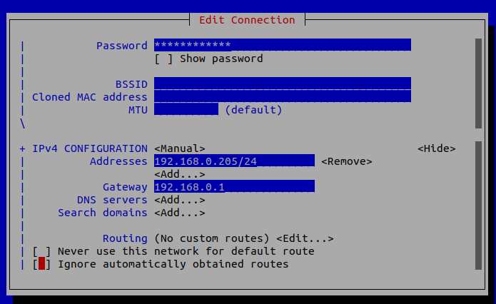
Let the laptop bootup with a fixed ip address:
run sudo nmtui, change the following in edit connection (to have a fixed address: 192.168.0.205)
network settings
Afterwards go to Activate connection.
Most likely requires a reboot (and access to a display instead of ssh if things go wrong).
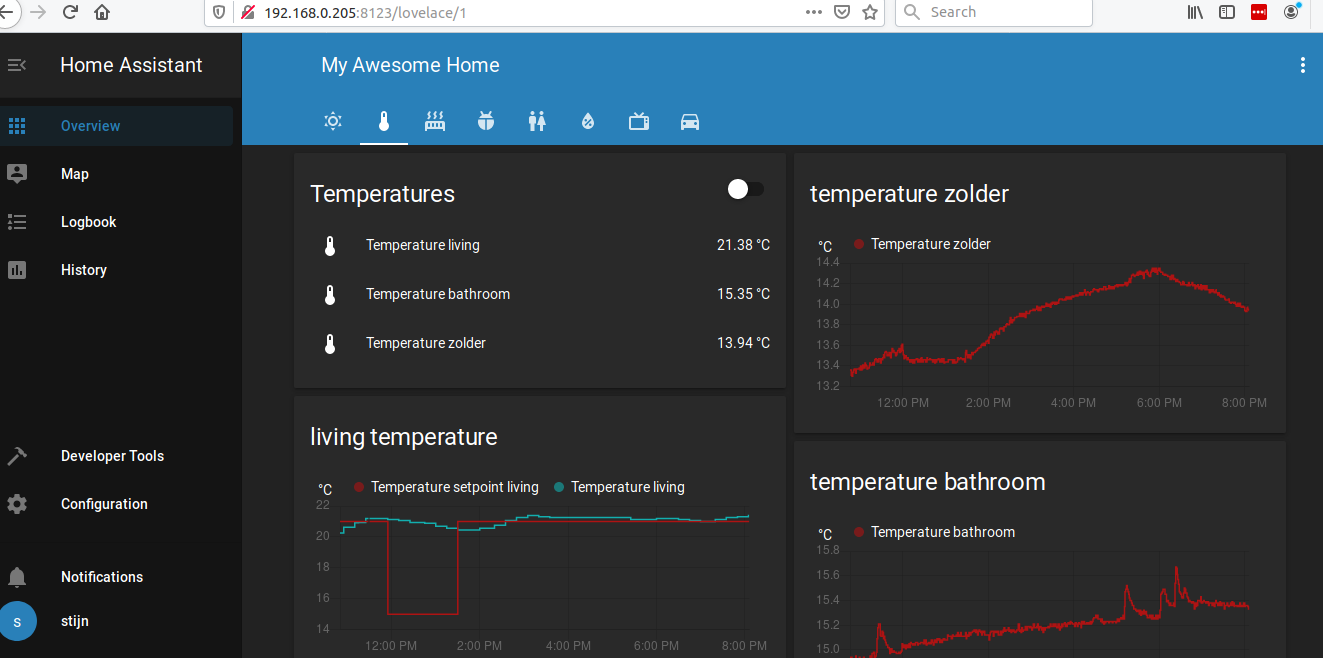
Result
hass interface
6 - Mail detection
Detects letters/post in the mail box (the physical mail box :) )
Detects mail and links it with homea assistant
6.1 - Mail detection version two
Goal
Get notified when a letter / package is dropped in your mail box (the real mail, not e-mail). Notifications are implemented by integration in my home assistant. Alternatives - sending an e-mail, text message, … - could be useful extensions.
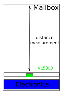
Concept
A distance sensor senses upwards in the mailbox, if a package is on top of it, the distance will be small. If the box is empty a larger distance is sensed.
The design is made to work with two AA-batteries (most common type in EU).
Concept
Short summary
An ESP8266 will send MQTT messages over wifi to report the distance measured in the mailbox.
There is a mismatch in voltage between two AA-batteries (2.4ish V) and the ESP (requires 3.3V). To avoid having a boost dc-converter turned on 24/7 and reduce battery life (significantly), the dc-converter and ESP will periodically get enabled/disabled by an Arduino pro mini.
The status of the ESP8266 gets communicated to the pro mini in a simple way.
The Arduino pro mini can work up to 1.8V. It does require setting the fuses of the microcontroller to the appropriate values. This will be done by burning a specific bootloader.
Compared to the first version of the mailbox detection, Tasmota will not be used. This to further minimize the time the ESP8266 is alive and connected to wifi.
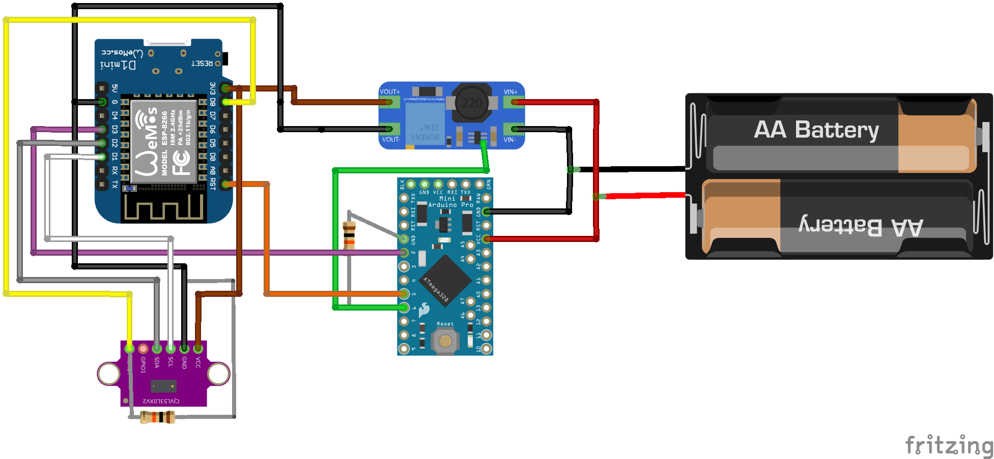
Layout
Wiring layout
Notes:
The pins has been selected taking the internal pullup and pulldown resistors into consideration. Consider this when making modifications.
To avoid unnecessary power losses, the wemos is directly fed to its 3.3V pin and not through the regular 5V (see the schematic of the Wemos mini). The same applies for the arduino pro mini (Vcc instead of Vraw)
Prerequisites
Of course, it’s fundamental wifi signals need to reach your mailbox :).
If not, you can already create wifi repeaters for less than 3 euro with an esp8266 / esp32 by using this software … .
Required components
Wemos D1 mini, to connect to wifi (and send mqtt messages)
MT3608: step up DC-DC to generate supply for wemos
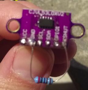
VL53L0Xv2 sensor, measures the distance accurately according the time-of-flight principle (for some reason much cheaper on aliexpress compared to banggood example)
Two AA-batteries
Few (10k) resistors
Another arduino or alternative to flash the pro mini as ISP, I’m using an arduino Mega 2560 but should work with all kinds of arduino’s or flash tools.
To reuse the available sketches for the Wemos, it is assumed an mqtt broker is available (in my case the board running home assistant). In case it’s not available, it shouldn’t be too cumbersome to make the Wemos send an e-mail or even a text message… .
Step 1: Flash bootloader on arduino pro mini
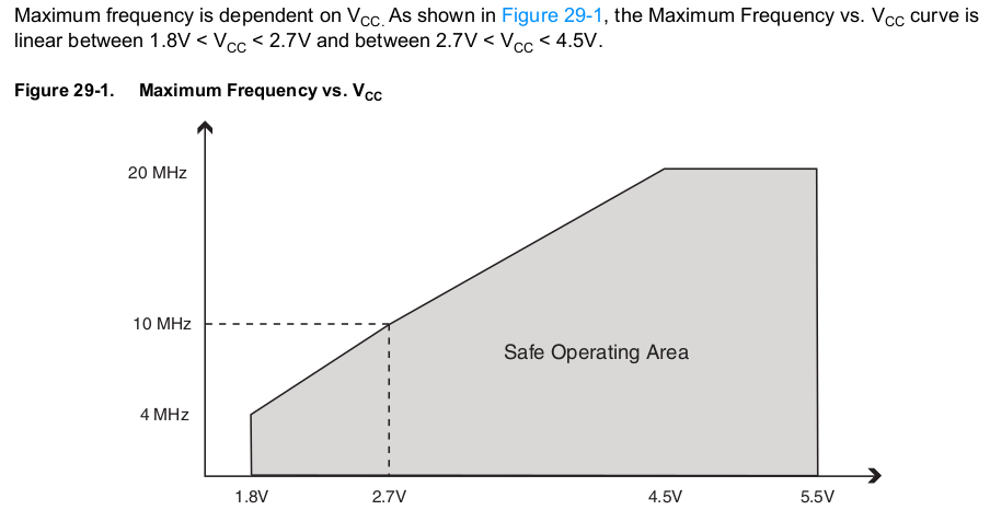
Why
According to the atmega328p datasheet, the frequency needs to be lower than 4MHz to be able to work at 1.8V. To achieve this we need to set the fuses of the chip, luckily this can be easily done in the arduino environment.
MHz vs minimum voltage
The lower the frequency, the lower the current consumption. Since the arduino doesn’t need to do anything fancy, there is no reason to choose a high frequency.
Programming using Arduino IDE
Prepare to program the pro mini through another arduino, you can find a lot of tutorials “Arduino As ISP” on the web (official arduino site). Double check in the ArduinoISP.ino sketch which pin is the reset pin, I’m using Arduino Mega 2560 as ISP which has pin 10 as reset pin.
upload the sketch from the default examples " ArduinoISP.ino" to your programmer (the Mega 2650 in my case)
make the wiring connections to the pro mini: MISO - MISO, MOSI-MOSI, SCK-SCK, RST (pro mini) to 10 (Mega), Vraw (pro mini) - 5V (Mega), GND-GND
open an example sketch like blink.ino to check if you can sucessfully upload. Select the board “Tools–>Arduino pro or pro mini”, Port remains the “arduino Mega” and upload the sketch using “Sketch –> Upload using Programmer” instead of the standard “Upload” button.
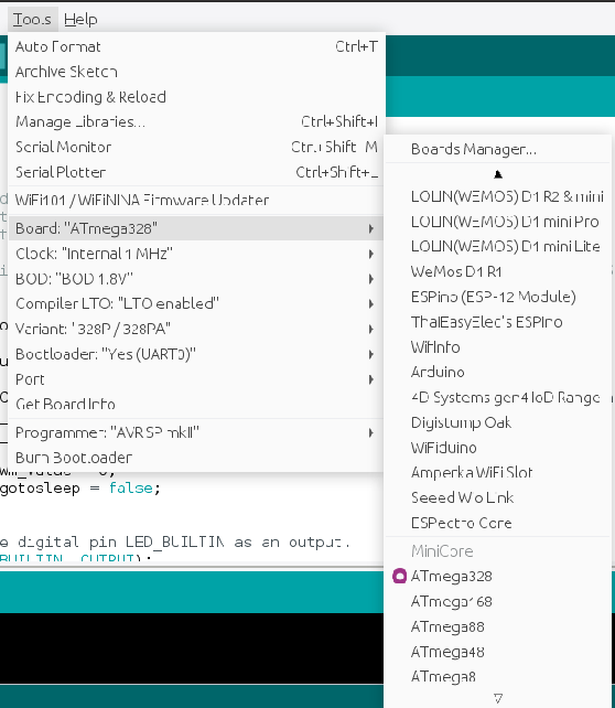
Burn bootloader (ironically, there is no need for a bootloader since we’re flashing following ISP. But if we don’t burn the bootloader, the fuses of the microcontroller don’t get set … .)
Select the following settings: ATmega328, Internal 1 MHz, BOD 1.8V, Variant: 328P, Bootloader: Yes
Arduino IDE settings
Press “Burn Bootloader”, if successfully programmed, reboot your pro mini
Upload a blink sketch “Upload using programmer”. Check the timing of the blinking led now we have changed the oscillator to 1 MHz instead of the default 8 or 16 MHz … .
LEDS
The power led and voltage regulator can be desoldered from the pro mini to decrease power consumption further. Don’t do this before debugging is finished.
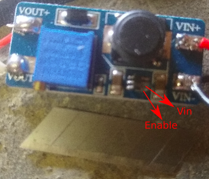
Step 2: Prepare DC-DC converter
This is by far the most finicky part of the setup. The MT3608 has by default an enable pin. Unfortunately this one isn’t easily available on the Chinese boards. You might want a few spare converters, just in case … ;).
Things to modify to the board:
Cut the trace between the enable and Vin pin. A fresh cutter knife seems just enough to do the trick.
MT3608 modification with cutter knife
Solder a wire to the enable pin. Do a beep test to make sure the wire is not connected to Vin+.
Test if the converter gets enabled and disabled by connecting the soldered wire respectively to Vin+ and GND/Vin-.
Finally, adjust the screw on the potentiometer till your output voltage becomes around 3.3V when the converter is enabled.
Step 3: Wire the components and program ESP and arduino
If this all went succesful, the hard work is over :).
Program the intended sketches on the pro mini (through the ISP method) and wemos. The sketches are available at https://github.com/goosst/MailboxDetection.
Some notes on key items to verify / adapt:
Wemos D1 Mini: one - rather remarkable observation - is that cycling input voltage from 2.3ishV to 3.3V, does not reboot the Wemos automatically. For this reason the ESP is put in deepsleep ESP.deepSleep(0); so it can be woken up through its reset pin. The deepsleep starts after a successful broadcast of a MQTT message. TTe pro mini needs to cycle the Reset pin of the wemos. Please verify this is working as expected, since the Reset pin is quite sensitive to be in a floating state.
Wemos D1 mini: in configuration.h change the password of your wifi and mqtt broker. Obviously you can change the name of the mqtt message if you want something clearer.
Arduino pro mini: check in the code how frequent you want to let the converter/ESP wake up and check your mail (by changing the counter in the for loop of 8 second sleep cycles).
  for (int i = 1; i < 20; i++)
  {
    LowPower.powerDown(SLEEP_8S, ADC_OFF, BOD_OFF);
  }
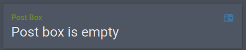
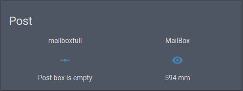
If everything is working, you should see periodic message of the distance being broadcasted in your mqtt broker. (Example below with messages arriving artificially fast every three minutes.)
if time_last>now-max_delay:
    #Check if empty (comparison in mm)
    if state_last<100:
        payload='{"state": "Check you post box!"}'
    elif state_last>=100 and state_last<1200:
        payload='{"state": "Post box is empty"}'
    else:
        payload='{"state": "No clue"}'
else:
    payload='{"state": "No update"}'
This script is called everytime the mailbox sensor (from the mqtt message) changes. This is done by defining this in configuraiton.yaml:
Xshut is active low, so it will try to pull pin D8 high. The big issue here is, GPIO15 should be low during the boot of the ESP8266 or the module will not boot up … .
Solution:
Connect Xshut to D8
add an additional pull down resistor to Xshut and GND (here using 2k ohm).
Additional resistor
Now pin Xshut is low during Deepsleep and high when the ESP is awake!
7 - Outdoor lighting
Switches outdoor light with sonoff flashed with tasmota
Switches outdoor light with sonoff flashed with tasmota
Goal
My outdoor lights give power outages when it rains a lot, the differential switch triggers (also when ligbts are not turned on).
Since the underground wiring cannot be easily fixed, a workaround was done by also switching the neutral wire going to the lights when power down.
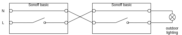
Concept
Double Sonoff switches
Tasmota settings:
PowerOnState 1: if the tasmota devices get power, they will turn on the lights automatically.
When the first tasmota gets turned on (by a manual switch or by homeautomation), the second tasmota will be turned on. When the second tasmota receives power it will turn on the lights automatically.
WifiConfig 5
SetOption1 1
SetOption13 1
Since the module is hidden in an electric box, the buttons on the tasmotas are disabled for certainty.
The different components
8 - Water level detection
Measures water height in well
Measures depth of water well and links it with homea assistant
Steps to create a virtual python environment using a specific python version (other than the version installed by default).
Steps
Install python version
Here using 3.8.4:
cd ~
mkdir tmp
cd tmp
wget https://www.python.org/ftp/python/3.8.4/Python-3.8.4.tgz
tar zxfv Python-3.8.4.tgz
cd Python-3.8.4
./configure --prefix=$HOME/opt/python-3.8.4 --enable-loadable-sqlite-extensions
make
make install
Install virtual environment
cd ~/tmp
wget https://files.pythonhosted.org/packages/aa/9d/d7713847ff3f58801045ab2ea5d4b6cdebc4a075b2bdd086f093beb92ecf/virtualenv-20.0.27.tar.gz
tar zxfv
tar zxfv virtualenv-20.0.27.tar.gz
cd virtualenv-20.0.27
~/opt/python-3.8.4/bin/python3.8 setup.py install
